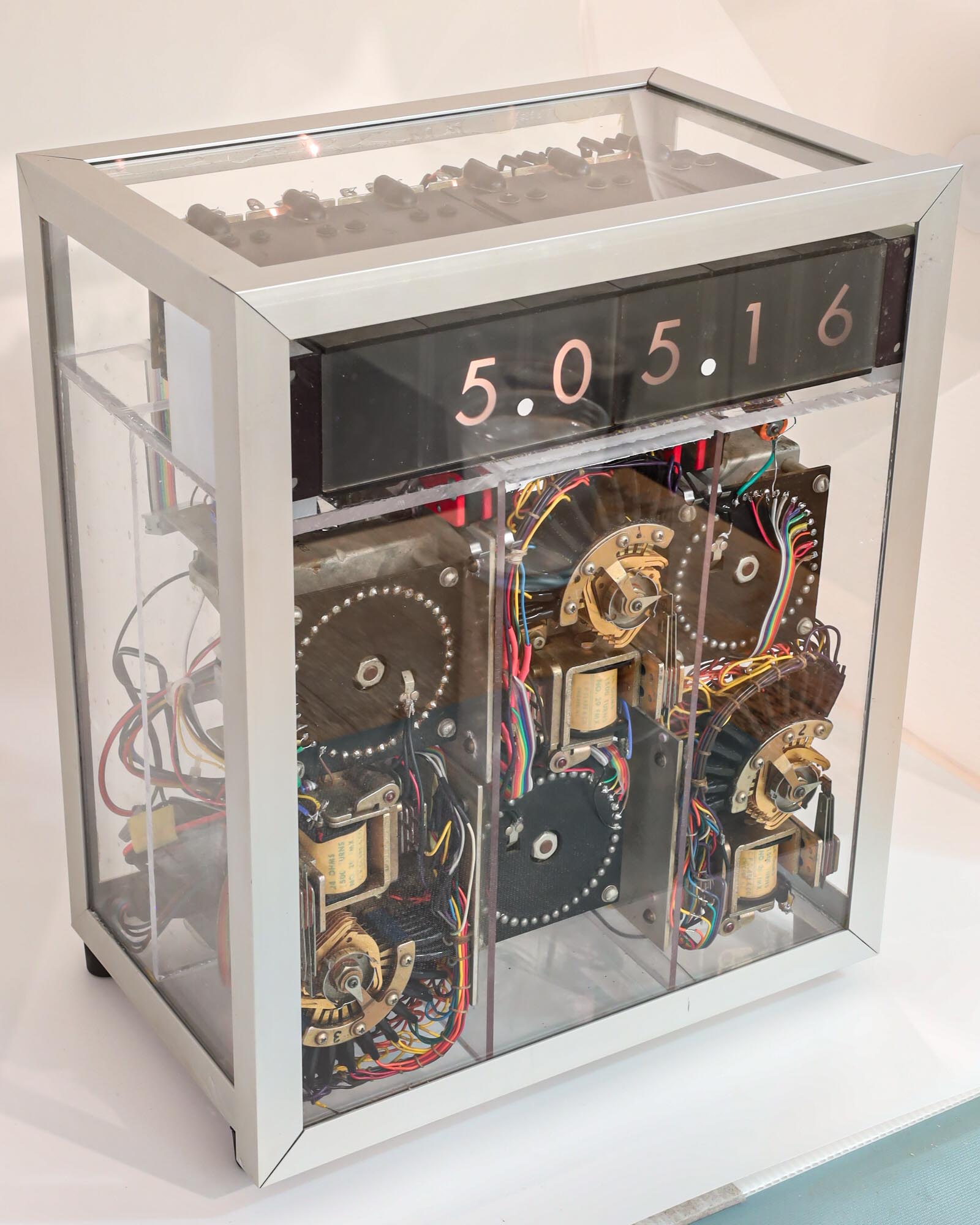
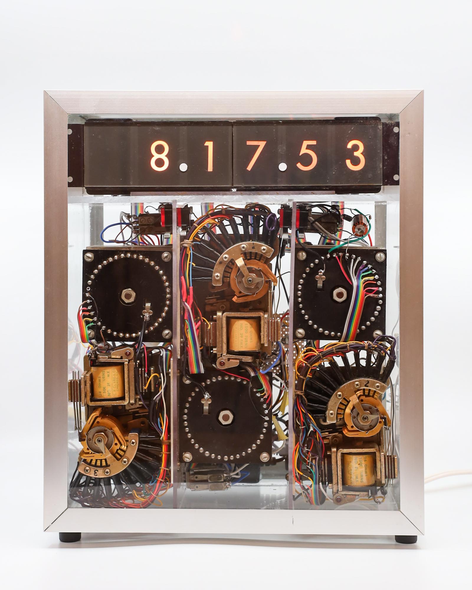
I have renovated the components of my nearly 50-year-old digital clock. The next step was to assemble it all back together. Would it actually work?
The old broken and abused internal plexiglass chassis was replaced by new plexiglass, providing an opportunity for me to learn the technique of plastic welding, where a syringe injects solvent into the edge of a surface-to-surface joint and spreads by capillary action to the full contact area, partially dissolving the plexiglass, which then forms new polymer bonds between the pieces. It takes a few minutes for it to start hardening, which gives some time to prop the parts in the desired position (use a square to get the angles right). It is completely cured in 24 hours and is truly “welded”. Like a good metal weld, a good plastic weld will break elsewhere if enough force is applied.
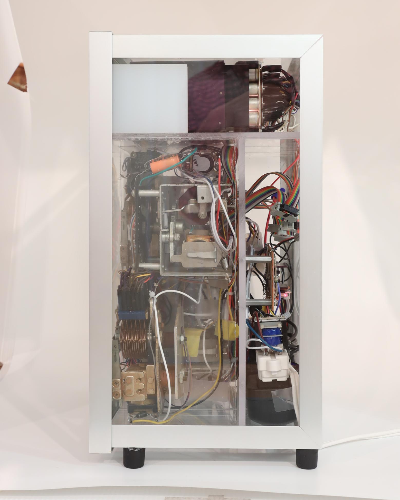
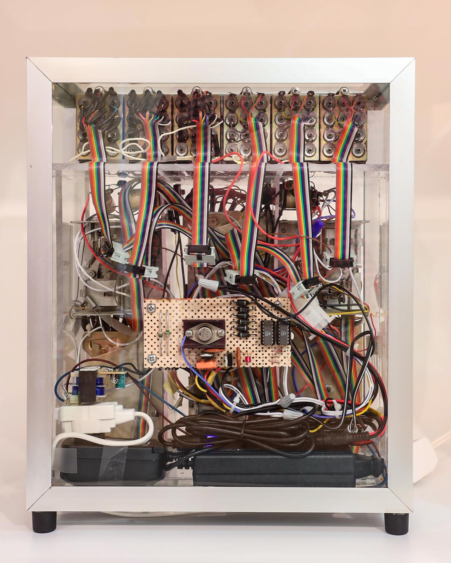
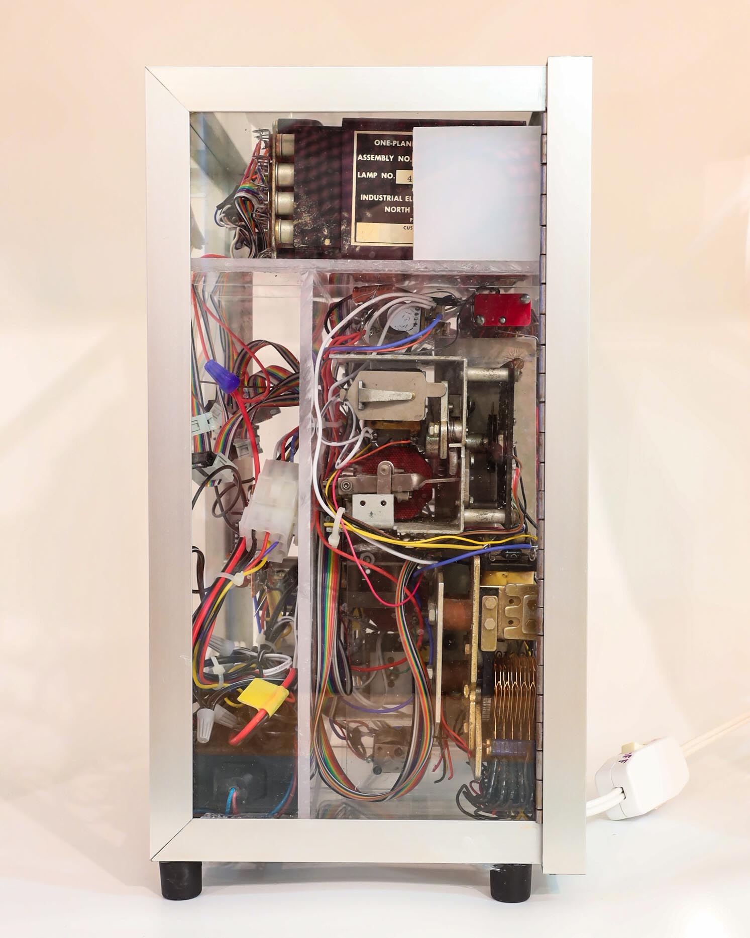
I mounted the new power supply components and logic board onto the chassis and placed the relay panels and display modules. I had re-wired nearly all of it, replacing the birds nest of old wires with new ones, bundled and dressed.
I tested the relays and found some problems with the carry pulses. The most problematic were the relays that counted 0 to 5, then on the increment to 6, needed to instantly reset back to zero. The contact at position “6” energized the reset coil, which brought the spring-loaded wiper back to the “0” home position. Unfortunately, as soon as the wiper started it’s quick travel (from “6” to “5”, “4” etc) , the reset coil instantly became de-energized and the return motion stopped, often at the “1” or “2” position. The carry pulse was cutting itself off before finishing.
I thought this was basically a race between the electrons in the relay coil and the mechanical contacts being pulled by the spring. Maybe lubricating the axle and contacts would let the wiper arm move more easily back to the home position, winning the race. But even the miracle “nano-oil” was unable to speed up the mechanism.
I spent quite a bit of time puzzling whether there was some clever wiring arrangement that would solve this problem. I never found it.
Eventually I realized that if I couldn’t speed up the mechanism, perhaps I could slow down the de-energizing of the coil. A diode and the right capacitor solved the problem. The coil stayed energized long enough for the wiper to make it all the way back to “0”.
I cleaned up and repaired the display case that I had built when I was in my early twenties. At that time I had learned how to make things with glass and the newly invented adhesive called RTV (for “room temperature vulcanizing”), now known as silicone sealant. It was a clear gel that as it cured with exposure to air, released a distinct vinegary acetic acid smell (familiar to me as stop bath solution used in developing film). The new sealant was perfect for making aquariums. I made terrariums in the shapes of dodeca- and icosa-hedrons (they have lasted for decades)! I used the same techniques to make a glass and aluminum case for my clock.
I assembled everything back together in the display case. My estimate for the power consumption is about 15 watts– 1 watt per display digit, and the rest from the one-second relay, which is energized 40% of each second– approximately 10 watts. When the door of the case is closed, one can feel the warmth on the glass, but it is certainly much less than I remember of the original.
The clock is every bit as loud as I recall, maybe even louder. I will likely not keep it running except to show it to curious visitors. I’m looking forward to explaining it to grandchildren.
My relay clock has now been restored. It has been a pleasant diversion during another covid winter. Unfortunately, it has reinforced my habit of keeping every project, finished or not, in the event that I might want to return to it. I have a few more old projects in storage. They will have to compete with new ones.
previous | The Relay Clock Restoration Project | next


Pingback: The Relay Clock Display | Thor's Life-Notes