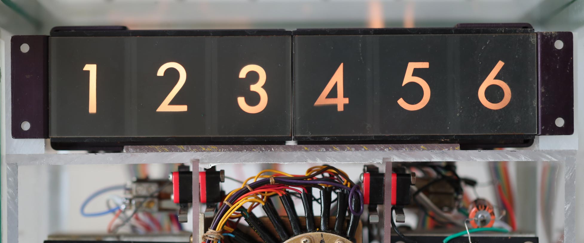
I recall seeing displays similar to this in elevators when I was very young, but it appears that these digital readouts came from a cockpit display or some other instrument. It seems rather impractical to me today, but digital displays were difficult to make back then, especially for the rugged environments found in aviation. I found a display similar to this being offered at a surplus site.

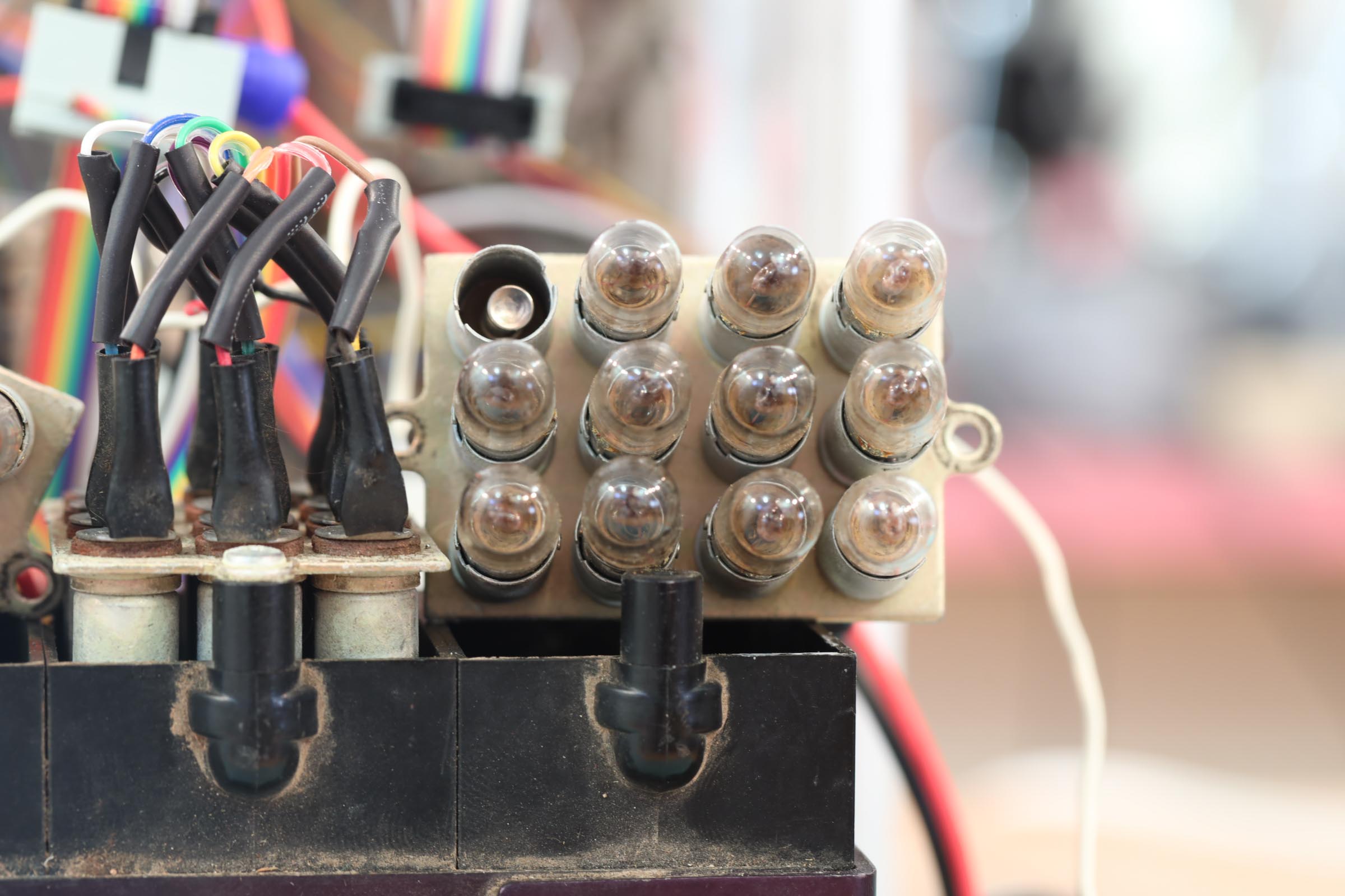
The basic idea is that there are ten light bulbs for each display digit. One of them is energized and lights up. It projects a numeric image onto a screen.
In this clock, the relay contacts direct a voltage to select a display digit. The relay coils operate at voltages of 12V, 24V, and 110V, but the display uses light bulbs that run at 6.3V, a common voltage used for vacuum tube filaments and pinball machine lights. You can see why 6.3 was a popular voltage, right?
I applied a test voltage to the lamps but found the display to be rather dim by today’s standards. Increasing the voltage brightened the projected number as one would expect. I wanted to boost the voltage further, but I recalled an observation by a colleague, Scott Mazar who, for no apparent reason, wanted me to know about an empirical measure of the lifetime of incandescent bulbs when their applied voltage exceeds their design voltage. As you increase the voltage, the bulb lifetime drops… dramatically.
There is a power law that uses an exponent of 12 to capture this relationship. For example if you applied 12 volts instead of 6 to a 6-volt bulb, its lifetime would be reduced by a factor of 2^12, that is, it will last 1/4000 of the design life. In the case of the GE-47, the bulb of choice for pinball machines and used in my aviation displays, the design life is 3000 hours. Running it at twice its voltage rating would burn it out in less than an hour!
Scott did not know that he was educating me for my future encounter with these old light bulbs. Like me, he simply has a curiosity about how things work, and he had never seen such a strong relationship among physical effects. Power laws are common in nature, but usually with exponents much smaller than 12! Scott could think of no other correlation in natural phenomenon that comes close to being so strong. This was the motive for him to let me know of this peculiar relationship.
Evidently, I was impressed when he told me about the 12-power law because it has stuck with me over the decades since, and advises me in this renovation project. I will be applying a little more than 6.3 volts to gain a bit of brightness, but not much more. I want it to last long enough to show it off to a next generation of inventors.

previous | The Relay Clock Restoration Project | next


Pingback: Wiring | Thor's Life-Notes
Pingback: Relay Resurrection | Thor's Life-Notes