[

I had planned to replace the inadequately designed power supply for the clock, and I had figured out how to update the signals to the relay coils, but I had really hoped that I could avoid re-wiring all of the individual connections between the relay contacts and the display bulbs (10 + 6 + 10 + 6 + 10 + 2 of them). I had figured out the connections and how they could be used with the new power supply without having to completely rewire them.
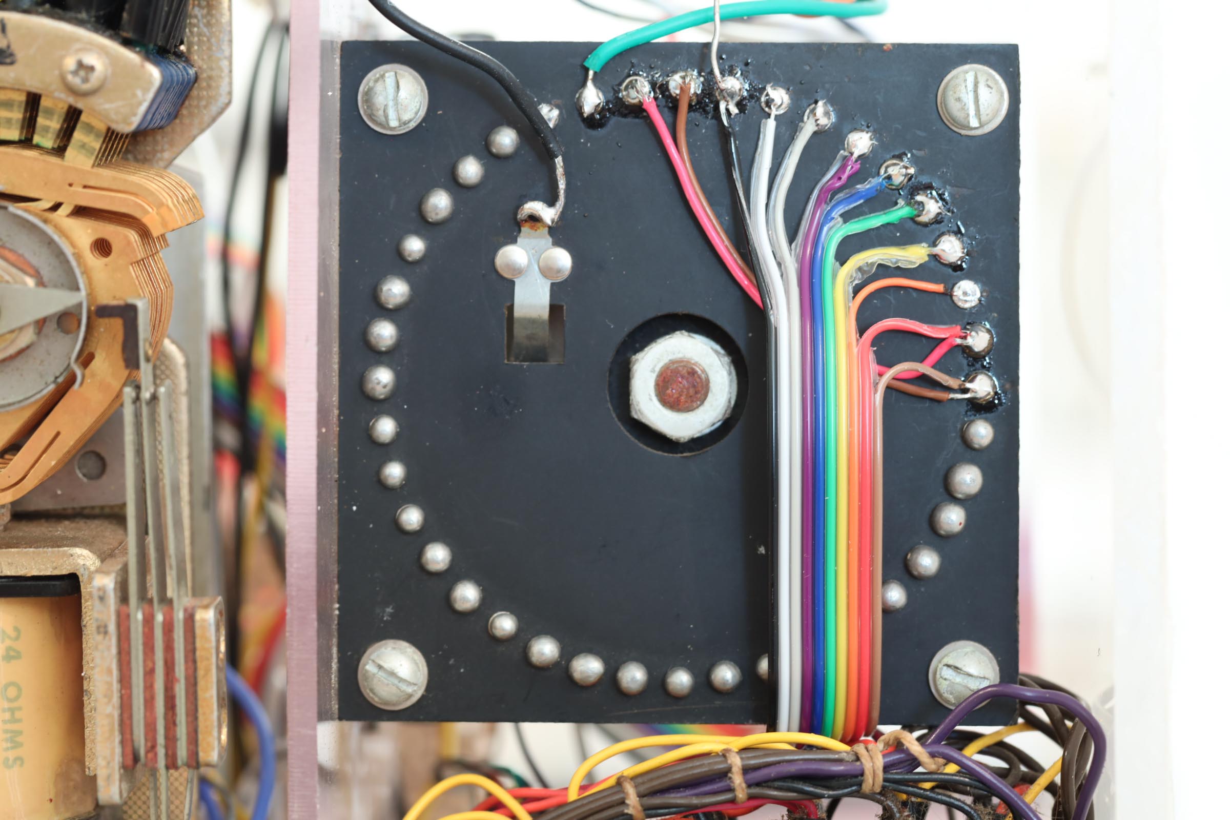
In 1973 I was using some of the latest technology, including “ribbon cable”, an evolutionary step from a tied cable bundle. Individual wires were laid side-by-side and cast in place with an insulating plastic bond. They were also called flat cables. Once again, my source of this unusual wiring system was from my dad’s ham radio shack.
I found them particularly appealing because they were color-coded with the series used to identify resistor values- black, brown, red, orange, yellow, green, blue, violet, gray, white to represent digits 0, 1, 2, … 9. They include the colors of the rainbow, and I recall thinking how nice they will look in the finished clock, which motivated me as I connected them to the stepper relays.
I used the ribbon cables to wire the relays to the displays, but in 40 years the cable bundles on the display had deteriorated and disintegrated, so they needed to be repaired. My plan was to replace the cable bundles with ribbon cable, and then connect them to the ribbon wire from the relays.
Flat-cable to flat-cable is a very common interconnect issue and an entire system has been developed for it called “insulation displacement connectors” (IDC). The wires in a flat cable are spaced 1/20th inch (0.05”) apart. The IDC connectors are plastic shells that host either pins or sockets spaced at the same interval. The pins and sockets are made of conductive metal, which at their other end become “spikes”. Using a crimping tool, the spikes pierce through the insulation of the flat cable and make contact with their respective conductive wires. Flat cables and IDC were a fast and accurate way to make multiple connections. Individual connections and bundling cables were rapidly replaced by it.
I ordered some ribbon cable and the male and female IDC connectors for the relay-to-display wiring in my clock. The color-coded ribbon wire provided a natural way to connect the display digits 0 to 9 to the color-coded ribbon wire from the relay contacts. I was pleased at how this part of the renovation was going.
Until I tried to install the IDC connectors. They worked fine on the newly re-wired displays, but when I tried to crimp their mates onto the old ribbon cable from the relays, I discovered that all ribbon cables are not alike. At least not across 40 years.
The old ribbon cable was at a tighter wiring pitch, maybe 0.04”. I suspect it was manufactured at a time prior to the settling on the 0.05” pitch as an industry standard. Whatever the explanation, my plan for the relays and displays to simply “connect them up” would not work. I concluded that the relays would need to be re-wired as well.
So I embarked on the re-wiring of the six stepper relays in the clock, something I had really hoped to avoid. But in the process I thought, “Well, this is a hobby; it’s what I do in my spare time which, as a retired person, is pretty much all of the time.” It is nice to be able to take on a project that has no deadline; to simply move ahead at the pace that provides the pleasure of incremental progress.
The whiffs of smoke from solder resin wafted by my face as I undertook this tedious task, and I thought of my dad, who first taught me the skills of making electrical connections by melting a tin-lead-flux alloy onto copper wires. It was a common scene to see him at a workbench, soldering wires together for his next experiment or gadget, something that might improve his ham radio station.
I’m not trying to enhance the performance of a radio transmitter or antenna, but I am enjoying the process of connecting basic electronic components to rebuild this artifact of an earlier time.

previous | The Relay Clock Restoration Project | next


Pingback: Early Integrated Circuits | Thor's Life-Notes
Pingback: The Relay Clock Display | Thor's Life-Notes
Pingback: Relay Resurrection | Thor's Life-Notes