Eclipse 2024 Reconnaissance

A road trip to Texas, May 2022

Introduction
In May, I made a solo road trip to Texas in order to do “reconnaissance” and to plan for the upcoming total eclipse of the sun on April 8, 2024.  I had made similar explorations of the western states prior to the 2017 Great American Eclipse which turned out to be very helpful in preparing for it.

You may ask “why Texas?”  It is not my usual road trip destination, but celestial mechanics is oblivious to human-drawn political maps.  It is also oblivious to weather, so to optimize the likelihood of clear skies on eclipse day, we need to be as far south and west along the eclipse path as possible.  Here is a chart of the cloud cover for the time in April along the eclipse path.

The various colors indicate the average cloud coverage at 2 p.m. Eastern time between April 3 and 13 based on ERA-Interim data from 1979 to 2016 collected by the European Centre for Medium-Range Weather Forecasting (ECMWF).  (Dr. Brian Brettschneider)

I’m not sure if this chart represents how much of the sky is covered, or how often the sky is covered, but it is apparent that Mexico is the best place to observe the eclipse.  Not eager to drive through Mexico, I am limiting the search to the US, which takes us to… Texas.

It turns out that the eclipse path runs through a pleasant part of south central Texas known as “Hill Country,” that contrasts with its flatter or harsher or more urban or more desolate areas.   For Texans, it is the equivalent of what Minnesotans call “Up North”, a place to escape the city, or to relax on vacation.  To me, it is not quite as nice as the North Woods, but I may be biased.

As I said, Texas is not my usual road trip destination.  I have not been to the state for decades, and, having observed Texas politics from afar, I am a bit intimidated.  But eclipse-viewing is something that can be enjoyed regardless of political view, so I packed up some observing gear and headed south. 

In the next series of blog posts, I’ll describe what I encountered along the way. If you enjoy my travelogues, or if you just want to glean information that might be relevant to your 2024 eclipse plans, I invite you to subscribe (meaning that you will get an email notification when I publish a blog entry).

next


Relay Resurrection

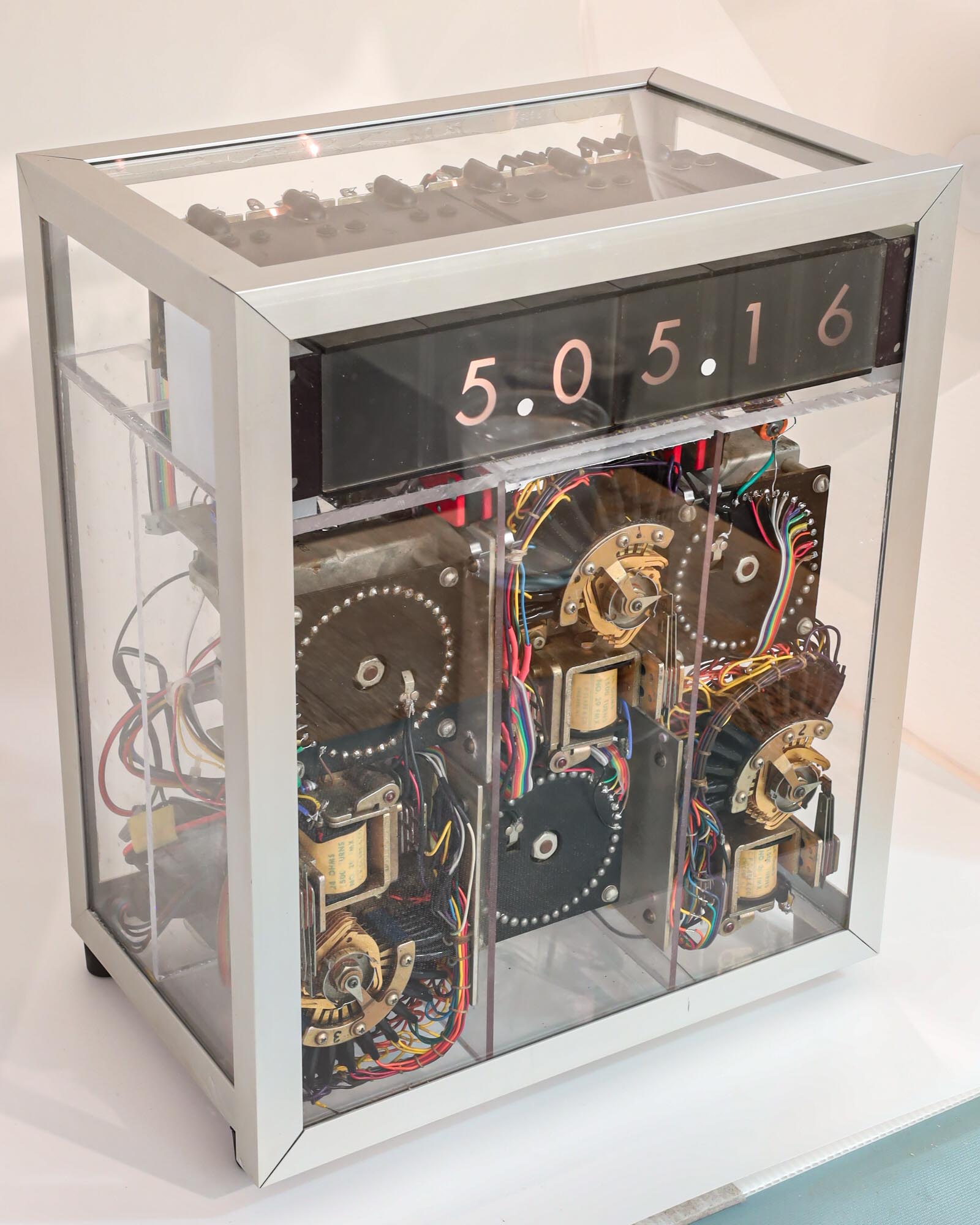
The restored relay clock, in its original glass case

I have renovated the components of my nearly 50-year-old digital clock. The next step was to assemble it all back together. Would it actually work?

The old broken and abused internal plexiglass chassis was replaced by new plexiglass, providing an opportunity for me to learn the technique of plastic welding, where a syringe injects solvent into the edge of a surface-to-surface joint and spreads by capillary action to the full contact area, partially dissolving the plexiglass, which then forms new polymer bonds between the pieces. It takes a few minutes for it to start hardening, which gives some time to prop the parts in the desired position (use a square to get the angles right). It is completely cured in 24 hours and is truly “welded”. Like a good metal weld, a good plastic weld will break elsewhere if enough force is applied.

Continue reading

The Relay Clock Display

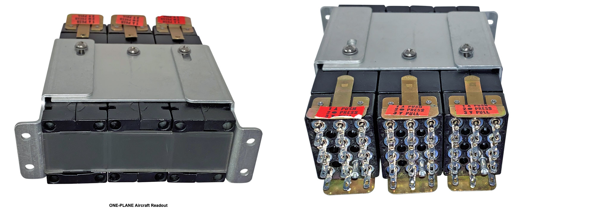
Digital readouts, probably from an aviation display

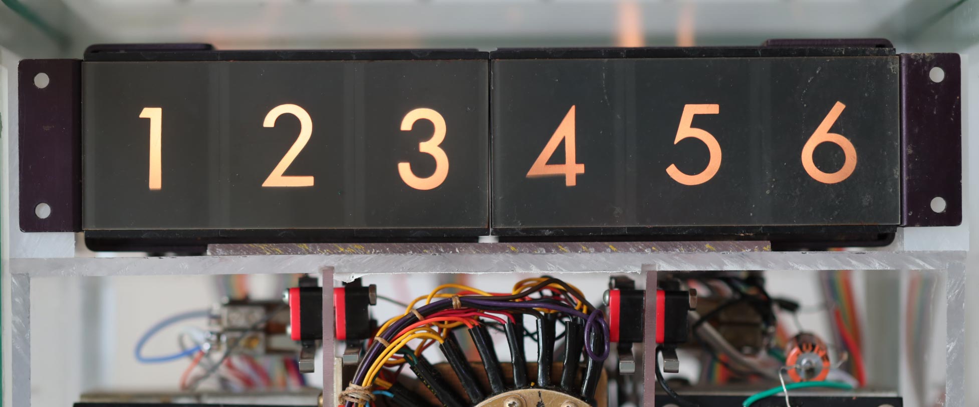
I recall seeing displays similar to this in elevators when I was very young, but it appears that these digital readouts came from a cockpit display or some other instrument. It seems rather impractical to me today, but digital displays were difficult to make back then, especially for the rugged environments found in aviation. I found a display similar to this being offered at a surplus site.

A front and rear view of a surplus aircraft readout. There was only one available, at a price of $150!


The basic idea is that there are ten light bulbs for each display digit. One of them is energized and lights up. It projects a numeric image onto a screen.

In this clock, the relay contacts direct a voltage to select a display digit. The relay coils operate at voltages of 12V, 24V, and 110V, but the display uses light bulbs that run at 6.3V, a common voltage used for vacuum tube filaments and pinball machine lights. You can see why 6.3 was a popular voltage, right?

Continue reading

Wiring

[

The back end of two three-digit display modules. On the right, the bundled cable wiring has been replaced by flat ribbon cable with insulation displacement connectors. The remnants of the old ribbon cable from the relays are seen on the left, individually soldered to the display lamp wires.

I had planned to replace the inadequately designed power supply for the clock, and I had figured out how to update the signals to the relay coils, but I had really hoped that I could avoid re-wiring all of the individual connections between the relay contacts and the display bulbs (10 + 6 + 10 + 6 + 10 + 2 of them).  I had figured out the connections and how they could be used with the new power supply without having to completely rewire them.

In 1973 I was using some of the latest technology, including “ribbon cable”, an evolutionary step from a tied cable bundle.  Individual wires were laid side-by-side and cast in place with an insulating plastic bond.  They were also called flat cables.  Once again, my source of this unusual wiring system was from my dad’s ham radio shack. 

I found them particularly appealing because they were color-coded with the series used to identify resistor values-  black, brown, red, orange, yellow, green, blue, violet, gray, white to represent digits 0, 1, 2, … 9.  They include the colors of the rainbow, and I recall thinking how nice they will look in the finished clock, which motivated me as I connected them to the stepper relays. 

Continue reading

Early Integrated Circuits

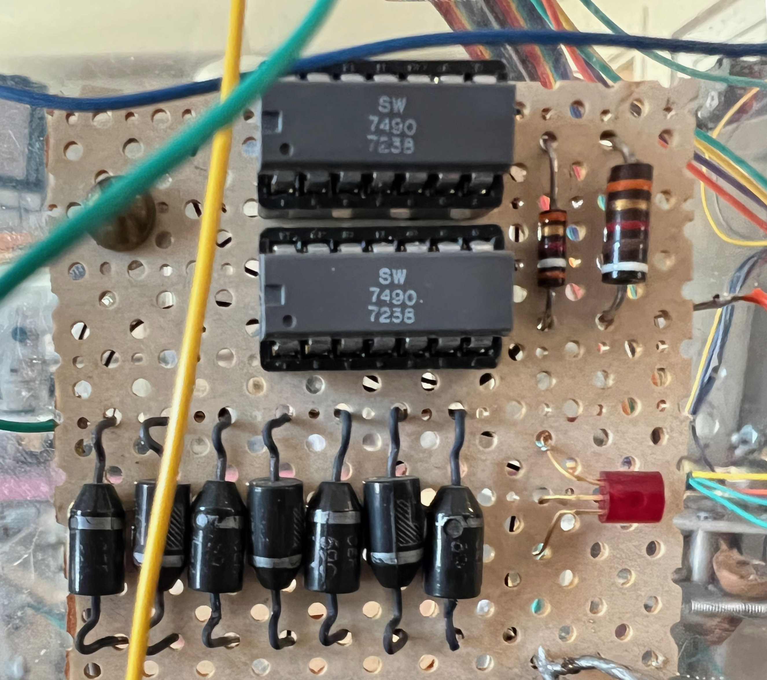
Two 7490 integrated circuits. The date code tells us that they were manufactured in September of 1972.

Although I was unaware of the new integrated voltage regulator circuits when I built this clock, I was familiar with an early series of integrated logic circuits, the 74xx TTL chips (TTL stands for “transistor-transistor-logic”). Again, the ability to replace multiple circuit boards of discrete components that implemented a specific logic function with a single integrated circuit chip, was revolutionizing electronics.

An example is the 7490, a small 14-pin device that implemented logic that could count to ten. I used two of them, configured to count to 60 and then start over. I fed it a clock input that was derived from the household AC line, 60 cycles per second, and it delivered a logic pulse once a second to the first relay in the clock.

I wanted to keep this relic of a circuit in the renovated clock, and so I adapted its input to the AC signal from the new power supply. But I had forgotten the rules for using the ancient TTL logic, which required much higher current than is used today. Modern CMOS logic uses almost zero electrons to do their magic, which is why your phone doesn’t discharge within a few minutes, blistering your hand with the heat.

My first attempt to trigger the old timekeeping logic resulted in paralysis. No ticks.

Continue reading

Modern Power Supplies

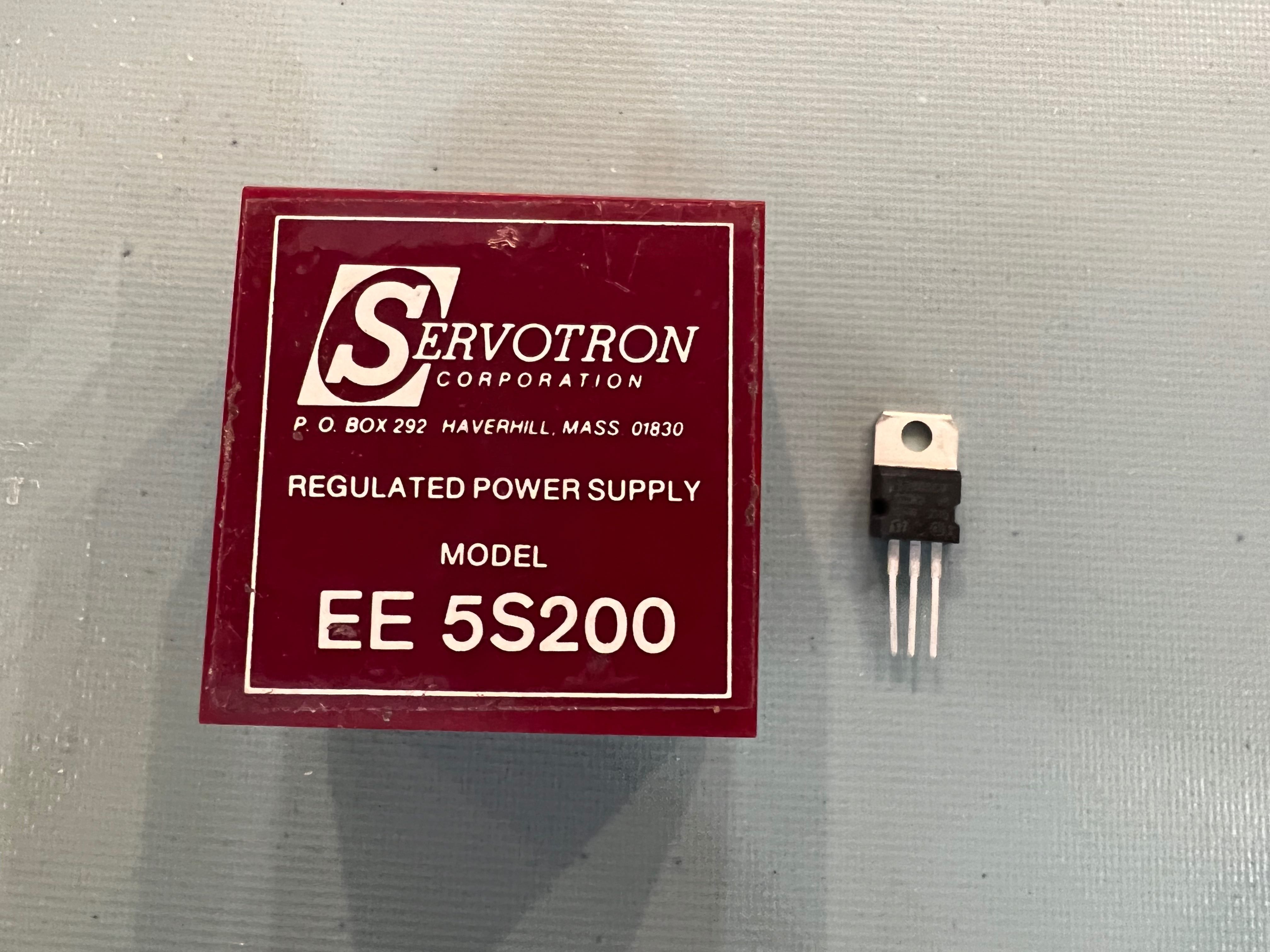
State-of-the-art power supply in 1973 next to a modern (for over 40 years now) voltage regulator.

As I mentioned, I was not skilled in power supply design in 1974. I am still no expert, but I have acquired some familiarity with them over my career. Back then, one needed to understand transformers and bridge rectifiers and capacitors. They were simple, but limited.

Think of your basic plug-in wall charger. A few years ago, they were made of a dense and bulky transformer, diodes, and a capacitor, the smallest components that the designer could find to meet the power requirement. They were not terribly efficient and could only provide a few watts.

Today your cell phone and computer chargers can deliver hundreds of watts but are smaller and lighter weight than those old “wall warts”. They are the beneficiaries of new power supply technology that uses high frequency internal circuits to replace the old iron cores of the 50-60-cycle transformers.

I could now replace my old 24V center-tapped transformer-based power supply with a modern “AC to DC converter” that could provide more power at higher efficiency than was possible back then.

I needed some more voltages: 12V and 5V. The old supply took the “center tap” of the (24V) transformer to provide 12 volts for those relays that needed it. The 5V for the logic circuit that generated the one-second pulse was obtained by a crude arrangement of diodes and resistors powered from the 12V line. I’m amazed it worked.

But that was what was available back then: diodes and resistors. Today it is trivial to generate stable power supplies by using the ubiquitous 78xx series of voltage regulators, a component that has three pins: voltage-in, ground, and voltage-out. These breakthrough parts were first manufactured in the early 1970s, a time when “integrated circuits” had recently been invented and were being applied to an ever-increasing number of applications. In this case, elaborate voltage regulation circuitry that had previously required dozens of discrete components were now implemented by microscopic semiconductor junctions contained on a single “chip”. At the time I built this clock, regulator chips were becoming available, but I did not yet know about them.

Today (and for the last 40+ years), I use the 7805 to provide a +5 volt supply, and a 7812 to generate +12 volts. This will be part of my power supply renovation.

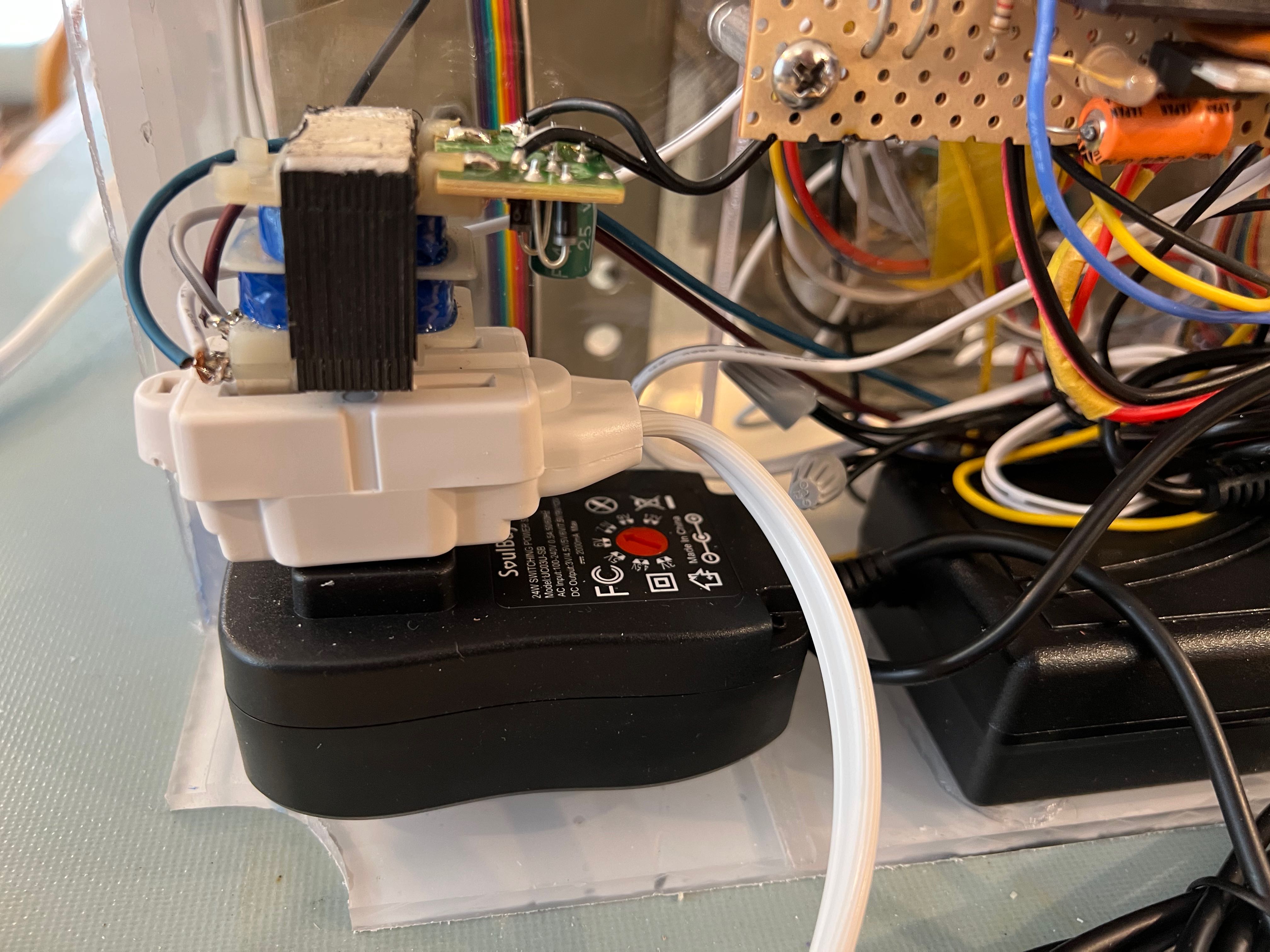
AC to DC converters (black modules) for the renovated clock. One provides 24V, the other supplies the 6.3V for the display lamps. The object plugged on top of the power cord is an isolation transformer that provides the primary timing signal.

previous | The Relay Clock Restoration Project | next


Restoration

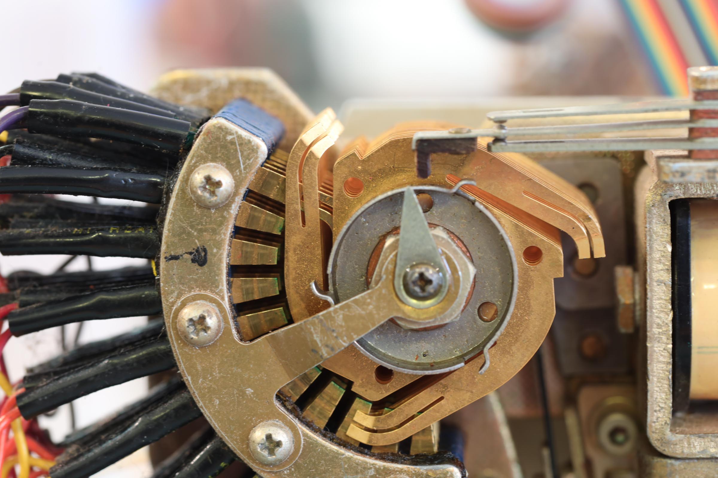
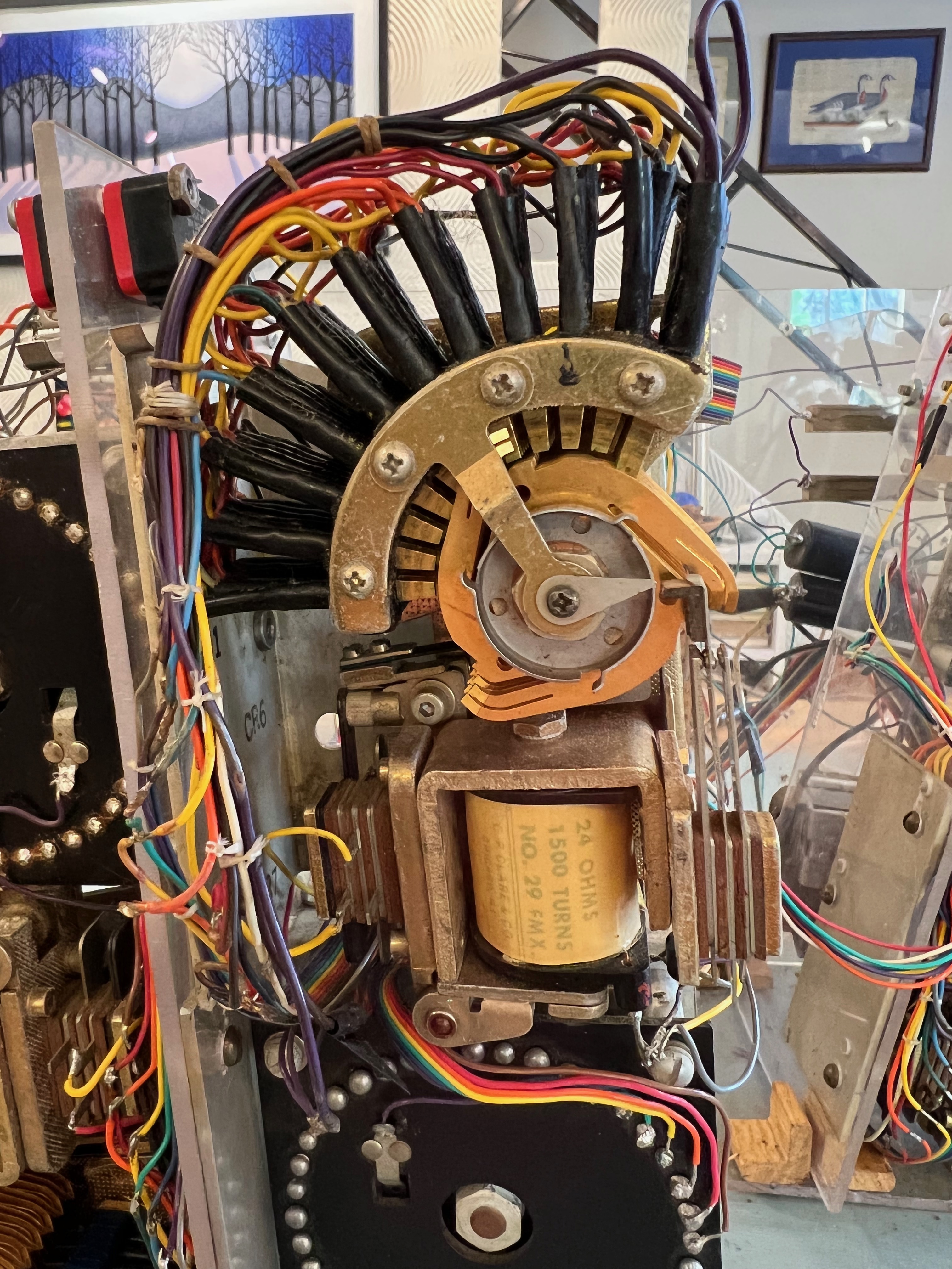
A closeup of the ten-step relay. It moved sluggishly and got held up on the tenth step when the carry contact (upper right) could not close, stopped by the bump on the circular cam.

I re-wired the relay coils for the improved control circuit and hooked up the new power supplies. A set of micro-switches were used for setting the time—they momentarily applied power to the relays with each button push. I could now see if the relays still worked. They did!

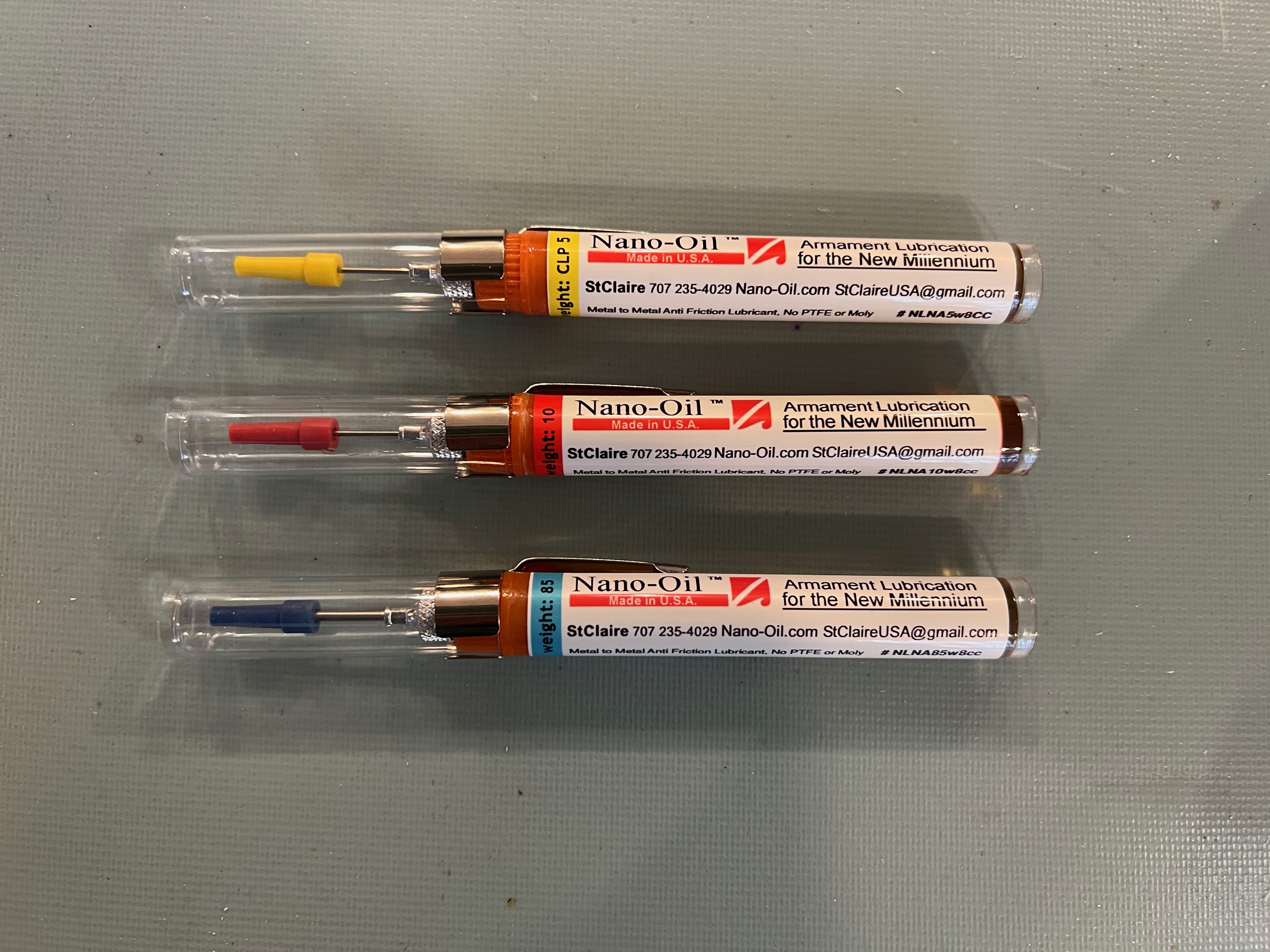
Well, they mostly worked. The contacts had tarnished and needed cleaning, and some of the mechanisms got stuck in one or more positions. I applied the usual treatment for things that stick—WD40, but it was not enough. The lubricant that finally allowed the decade stepper relays to move freely was something called “Nano-Oil”, a substance using “Magnetically induced Molecules of 0.09 microns”, that my son had gifted me a few years back. At the time I wondered what I would use it for, but he evidently saw my future need for it.

“Nano-oil” helped to re-lubricate the moving parts on the relays.
A short video showing the (restored) relay activation and contact movement.

previous | The Relay Clock Restoration Project | next


Reverse Engineering

I had no schematic and my memories were vague, but I recalled that there had been three types of relays, all operating at different voltages, which made for a complicated arrangement of relay contacts and coil terminals. There was yet another voltage involved in lighting up the display. I wanted to figure out how I had managed all this complexity back when I barely understood power supplies, and then figure out how to renovate it, with the least amount of re-wiring.

As I went about tracing wires, confirming contacts with an ohm-meter, I gradually built up a re-understanding of how the relays were interconnected. Some of the wires had broken and so I could only guess their destinations. I eventually figured out how the three different relay types managed to propagate the time signal from one level to the next. As I worked on this, there were more than a few times when I wondered “how could this have ever worked?”

Continue reading

The Relay Clock

It may not look like it, but this is a clock, one of the world’s first digital clocks, circa 1973.

When I was twenty or so, I built a clock. It was a clock that used electromechanical relays to count the seconds, minutes and hours. I was early in my electrical engineering studies and barely understood Ohm’s law, but I was aware of electromagnets, and how they could be used to make mechanical movements. Some of us call them solenoids, coils of wire that magnetically push or pull an iron piston to make and break switch contacts.

My dad, in his ham radio hobby quest for cheap electronic components for whatever future project he might undertake, had acquired various relay mechanisms. He showed them to me and explained how they used electrical pulses to move a metallic wiper to a series of successive contacts. These were telephone relays, used when you “dialed” the phone. One relay, responding to a single rotary dial action could connect you to ten possible neighbors. Cascading it with another set of relays would allow calling up 100 neighbors. More phone digits would extend it even further, you get the idea. I barely understood how to deliver current to energize a relay coil, but I could figure out how to connect the contacts to make a sequence that counted.

Another item from my dad’s ham shack inventory of salvaged components was a numeric display, something you might see in an elevator (60 years ago) indicating the current floor. It used incandescent light bulbs to project a numeric figure on the screen. Ten separate bulbs, each behind a number glyph mask; one of which was selected for the current digit value. I figured out how to connect the telephone relays to the elevator displays to make a clock.

I was quite pleased with the result and when I got it working, I showed it off to my friends. But it had several drawbacks. First, it was noisy. Relays are mechanical devices that magnetically pull metal contacts against each other, resulting in a click-clack noise as they activate and release. The relays counted seconds, so there was a click-clack noise every second. And at ten seconds there was an additional click-clack, as the next relay responded to the carry pulse. And at 59 seconds, there was a carry to the minute-counting relay. As the carries propagated to the hours, a peak acoustic disruption occurred as the clock transitioned from 12:59:59 to 01:00:00.

The other drawback was that the clock got hot. As I said, I did not yet understand the relationships of voltage, current, power and heat. I just hooked up the components to make the displayed result I wanted. The numeric display, comprising light bulbs, used quite a bit of power. And the relays required power too, and my power supply was terribly inefficient. As a result the clock, in the glass case I made for it, built up an enormous amount of heat. I tried to ameliorate it by installing an internal fan, but this seemed only to make things worse (the fan used power too).

I kept the clock as a curiosity piece, displayed on a fireplace mantel in our home. It was intolerable to run continuously, so I would switch it on to show visitors that it actually worked, and then shut it down to stop the noise. Eventually, the clock got packed up during one of our moves and stayed so.

The boxed-up relay clock was in storage for at least 30 years, but I would occasionally encounter it hiding among my workshop parts and supplies. I recently ran across it. It had endured the desecration by (and excrement of) rodents, the decay of electrical components, and the binding of mechanical joints. I wondered why I had saved it all these years.

Well, the idea of resurrecting a contraption that I built half a century ago carried a certain appeal to me. Having since learned the principles of electricity, maybe I could bring it back to life and its former geek glory!

In the next series of posts, I will describe the process of restoring this pioneering clock.


next


“Coffee Table Nightscapes” goes to print!

I finally caught up with my blog postings of past nightscape photos to reach the ones I made this last year. And I have now completed their assembly into a printed photo book.

I didn’t realize when I started this project that the pictures would span 25 years, and that they happened to straddle the transition from film photography to digital. The chronological order reveals the change in technology as I pursued my various night sky targets.

For completeness, I posted the preface and introduction as blog entries, but their real place is in the leading pages of the printed book where all the photos are collected under one cover. I was pleased to be able to give copies of it to my family and close friends this holiday season. Not all of them have coffee tables, but I hope they find a place for it.

Although this marks the end of this particular project, I doubt that I am really done. As mentioned in the epilogue, the capabilities of cameras just keep improving and so I am now excited to start the next 25 years of taking pictures of the night sky!