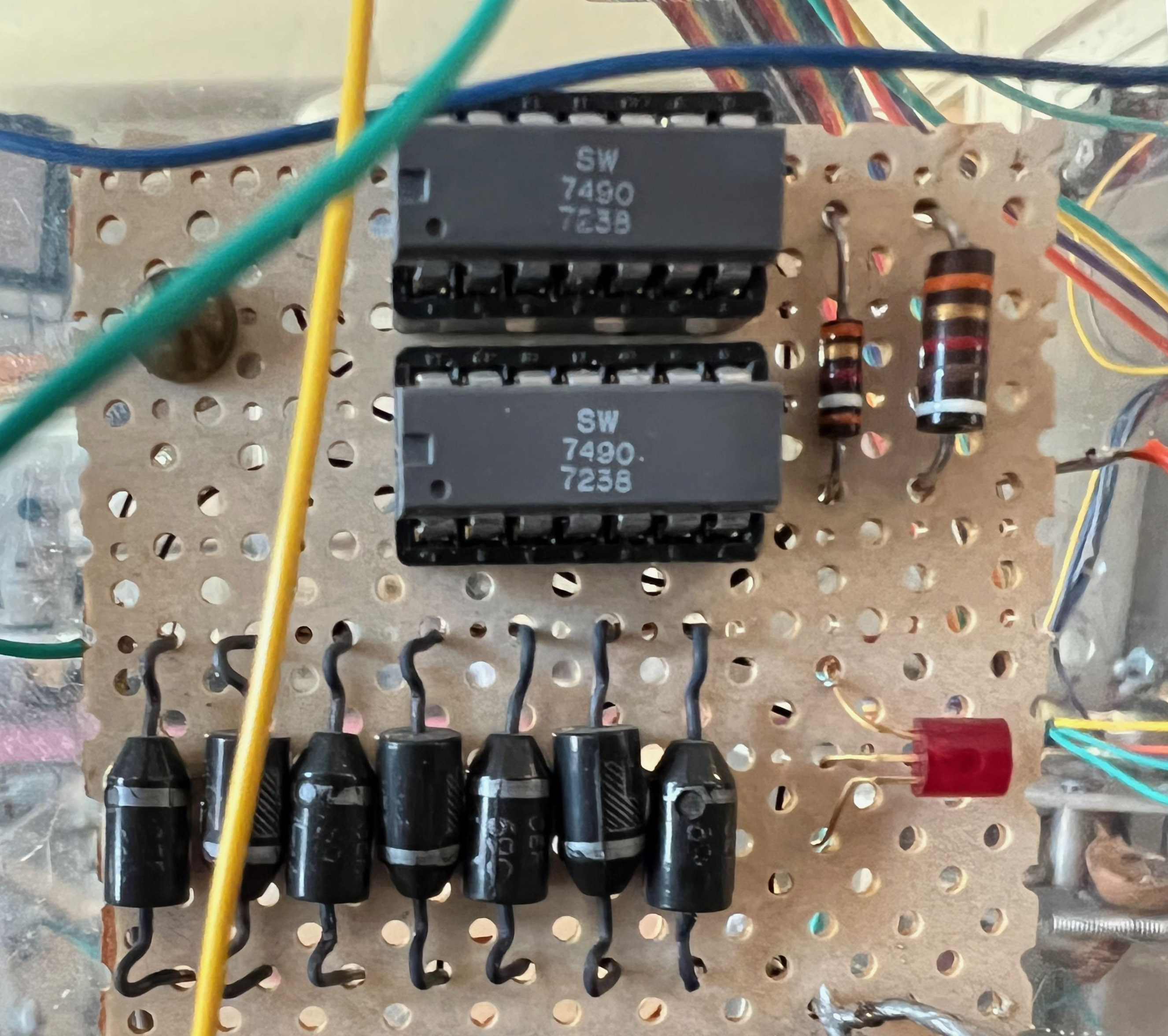
Although I was unaware of the new integrated voltage regulator circuits when I built this clock, I was familiar with an early series of integrated logic circuits, the 74xx TTL chips (TTL stands for “transistor-transistor-logic”). Again, the ability to replace multiple circuit boards of discrete components that implemented a specific logic function with a single integrated circuit chip, was revolutionizing electronics.
An example is the 7490, a small 14-pin device that implemented logic that could count to ten. I used two of them, configured to count to 60 and then start over. I fed it a clock input that was derived from the household AC line, 60 cycles per second, and it delivered a logic pulse once a second to the first relay in the clock.
I wanted to keep this relic of a circuit in the renovated clock, and so I adapted its input to the AC signal from the new power supply. But I had forgotten the rules for using the ancient TTL logic, which required much higher current than is used today. Modern CMOS logic uses almost zero electrons to do their magic, which is why your phone doesn’t discharge within a few minutes, blistering your hand with the heat.
My first attempt to trigger the old timekeeping logic resulted in paralysis. No ticks.
I eventually looked up and found on the internet a data sheet for the old 7490 (a part that was designed 20 years before the internet even existed, and was entirely obsolete by then) and located its electrical characteristics. It told me that my high-impedance low-power input signal would be completely invisible to this vintage 1970s era chip! It was like trying to power a toaster with a watch battery.
So I made a few adjustments, reverting back to how logic circuits were designed back in those days. It’s not low power, but then the counting logic is the least of the power consumers in this clock.
I have been asked why I used the 60 cycle per second AC power as the timebase for the clock; wouldn’t it be better to use a timing chip?
Well, timer chips had been invented by 1970. In fact the famous 555 timer chip was all the rage for electronic hobbyists. But the timer chip accuracy was only as good as the electronic components used– the resistors and capacitors– and their stability with temperature, humidity, and aging. Over time, the clock would drift. Early digital clocks and watches, used low frequency crystals that resonated at 32,768 beats per second. The watch logic used 15 stages of a divide-by-two circuit to generate a one-second signal. But even the crystal-based time keeper drifted over time and temperature.
The AC power that comes into everyone’s home oscillates at 60 cycles per second, which is the rotation rate of the generators, driven by steam turbines at the power plant. One might expect that it would drift depending on how much power is being used and the capacity of the generators. And it does. On high load days, the generators fall behind slightly; on low load days they might run a little fast.
But the operators at the power plant are monitoring these slight deviations, and then compensate with the controls they have on the turbines so that any lag or lead in the number of cycles the generator has delivered is brought back to an average of 60 cycles per second. This is why the clocks on the walls of schools, workplaces, hospitals, and any other clock using an AC motor plugged into the power grid never needs adjusting, except perhaps for daylight savings time (and after actual power outages).
previous | The Relay Clock Restoration Project | next


Pingback: Modern Power Supplies | Thor's Life-Notes
Pingback: Wiring | Thor's Life-Notes
Pingback: Relay Resurrection | Thor's Life-Notes