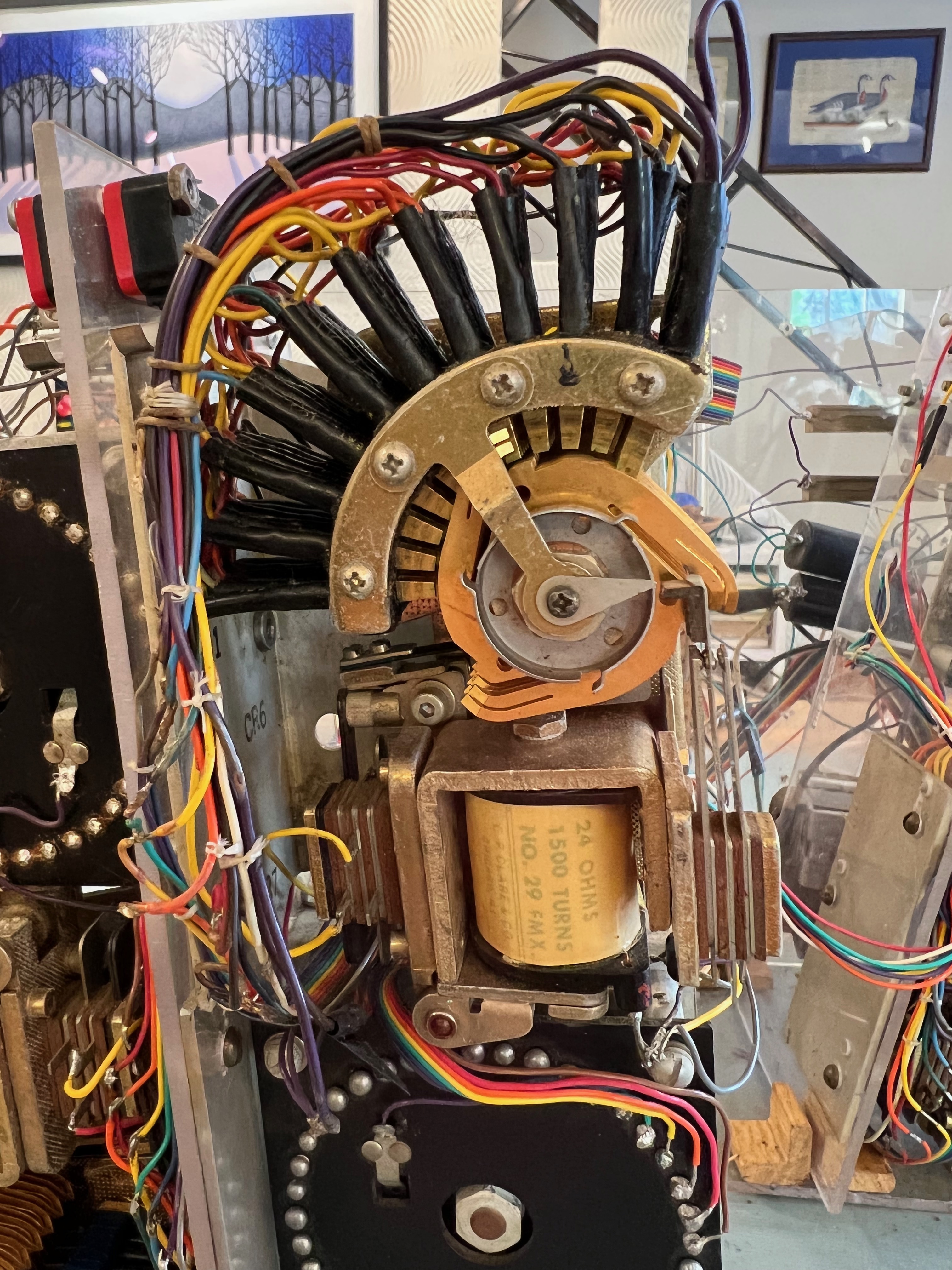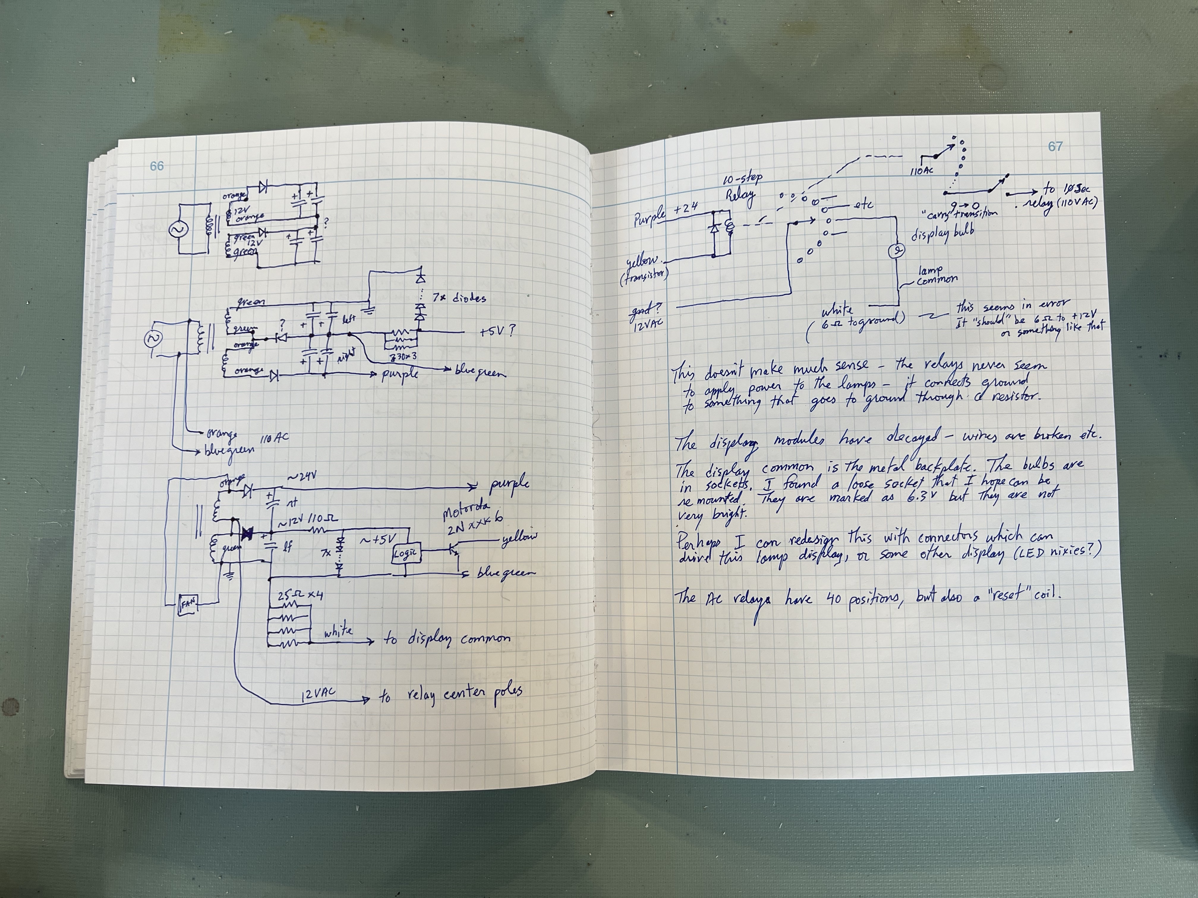
I had no schematic and my memories were vague, but I recalled that there had been three types of relays, all operating at different voltages, which made for a complicated arrangement of relay contacts and coil terminals. There was yet another voltage involved in lighting up the display. I wanted to figure out how I had managed all this complexity back when I barely understood power supplies, and then figure out how to renovate it, with the least amount of re-wiring.
As I went about tracing wires, confirming contacts with an ohm-meter, I gradually built up a re-understanding of how the relays were interconnected. Some of the wires had broken and so I could only guess their destinations. I eventually figured out how the three different relay types managed to propagate the time signal from one level to the next. As I worked on this, there were more than a few times when I wondered “how could this have ever worked?”
The first relay type was one that counted seconds and minutes 0 to 9. This used the ten position stepping telephone relay. It required 24 volts at a high current, but it had multiple “poles”, so was able to switch the display digit on one set of contacts, and to power a “carry” pulse to the next relay on the second pole when it reached “9” and made one more increment.
The second relay type counted tens of seconds and tens of minutes. It had only a single pole that had 40 positions and was energized by 110 volts, household AC power. I had wired it to use the first six positions 0 to 5, and when it reached 6, the third type of relay was used to create a “reset” that brought the spring-loaded relay contact back to its home position.
The reset pulse was used as the carry from tens of seconds to minutes. Also from tens of minutes to hours.
Counting hours used a different strategy. The 40 position AC relay was wired to count to 12, resetting at 13. At position 10 and 13, a carry pulse incremented the next relay, which counted tens of hours, with the display alternating between 0 and 1.
The third type of relay was much simpler; it was a 12 volt automotive relay that had two positions, contacts closed or open, in a double pole single throw switch. When energized, it connected the wires together, which communicated a carry pulse from a DC relay to an AC relay (or vice versa) at the next stage.
So all together, the clock used three relays of each of three different voltages: 12VDC, 24VDC, and 120VAC. I discovered that my earlier self had incorporated an immense amount of wiring complexity to do this. My reverse engineering took several days and many pages of revised circuit drawings in my notes to figure it out.

The wiring was “backwards” from how I planned to apply the new power supplies. The old relay contacts switched the active voltage; the new plan was to have them switch common ground. This would make it easier to have multiple voltages being used for the various clock components. The circuit and its schematic would be simpler and more apparent to anyone reading it.
I don’t really expect that this clock will ever undergo a future renovation, but just in case, I take some minor comfort that it will at least make sense to the person dedicated or crazy enough to take it on.
previous | The Relay Clock Restoration Project | next


Pingback: Restoration | Thor's Life-Notes
Pingback: The Relay Clock | Thor's Life-Notes