We travelled by van to Talkeetna, the gateway of Denali National Park, passing through spectacular mountain vistas. By accident, I learned that there were vacancies on a sight-seeing small-plane tour into the park, and on a last-minute realization that the skies were clear and I would not likely be here again any time soon, I booked the flight! It was an amazing experience. Here are a few photos and a video sample.
Two hours northeast of Fairbanks is a feature that is the focal point of a rustic resort, Chena Hot Springs. The resort has been augmented by a geothermal power plant, greenhouses, and tourist attractions including the “Ice Museum”. We spent an afternoon visiting, ending with a soak in an outdoor pool fed by the springs.
Click a thumbnail, then scroll through.
The entrance to the Ice Museum, a tourist attraction at Chena Hot Springs, a two-hour drive from Fairbanks.Inside the Ice Museum. For $600 one can spend a night in one of their “ice hotel” rooms.One of the many ice sculptures on display here. The greatest risks to them are sublimation and teenagers.The Ice Bar. One could pre-order martinis, served in sculpted ice-martini glasses.The ice sculptor at work.The tradition is to make a wish and smash your ice-glass, but someone left theirs to sublimate in the snow.The Spring weather is exposing the cars left in the parking lot since Fall. Their wheels are on the pavement a foot or more down from the current driving surface of compacted snow.The hot springs provided a pool for us to enjoy the contrast between geothermal waters and winter snow!A young moose, working its way through the deep snow.
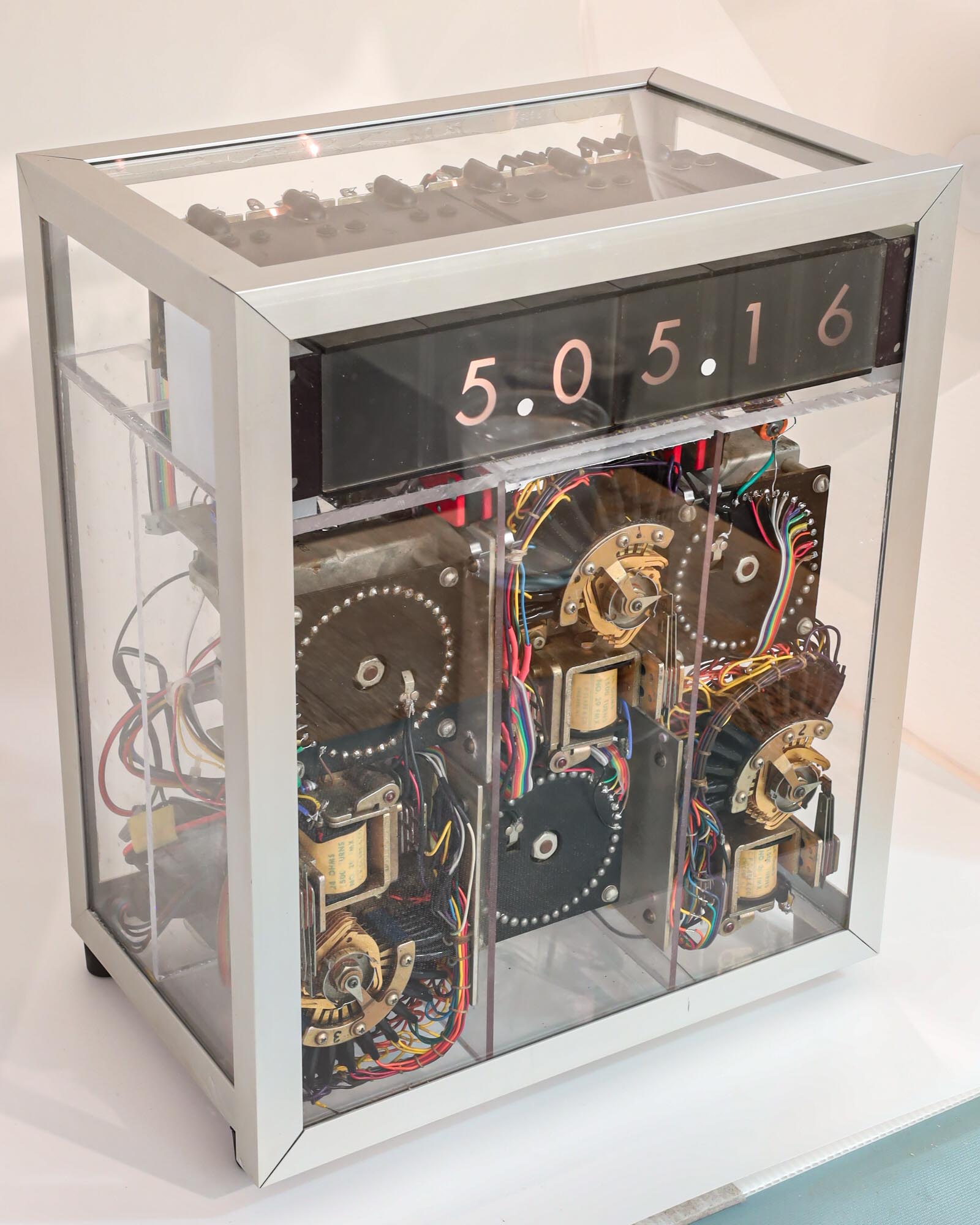
The restored relay clock, in its original glass case
I have renovated the components of my nearly 50-year-old digital clock. The next step was to assemble it all back together. Would it actually work?
The old broken and abused internal plexiglass chassis was replaced by new plexiglass, providing an opportunity for me to learn the technique of plastic welding, where a syringe injects solvent into the edge of a surface-to-surface joint and spreads by capillary action to the full contact area, partially dissolving the plexiglass, which then forms new polymer bonds between the pieces. It takes a few minutes for it to start hardening, which gives some time to prop the parts in the desired position (use a square to get the angles right). It is completely cured in 24 hours and is truly “welded”. Like a good metal weld, a good plastic weld will break elsewhere if enough force is applied.
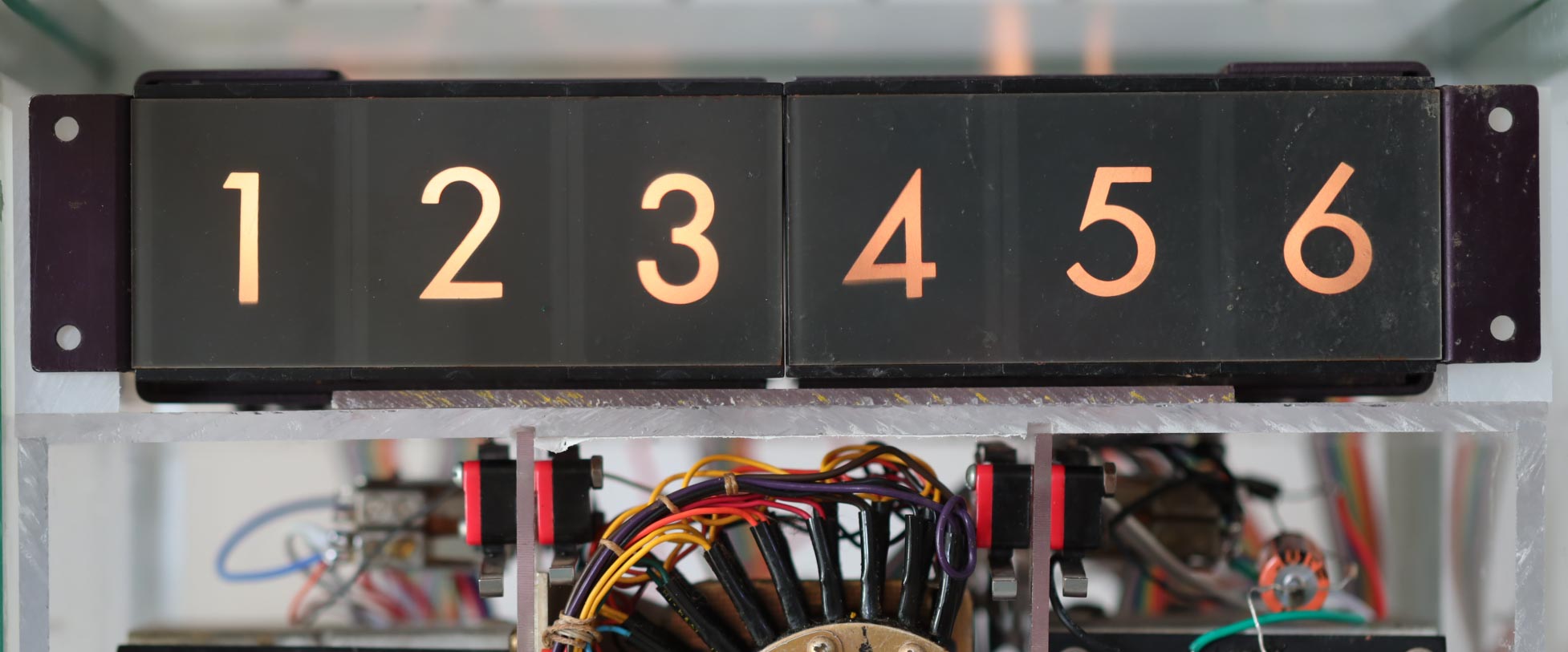
Digital readouts, probably from an aviation display
I recall seeing displays similar to this in elevators when I was very young, but it appears that these digital readouts came from a cockpit display or some other instrument. It seems rather impractical to me today, but digital displays were difficult to make back then, especially for the rugged environments found in aviation. I found a display similar to this being offered at a surplus site.
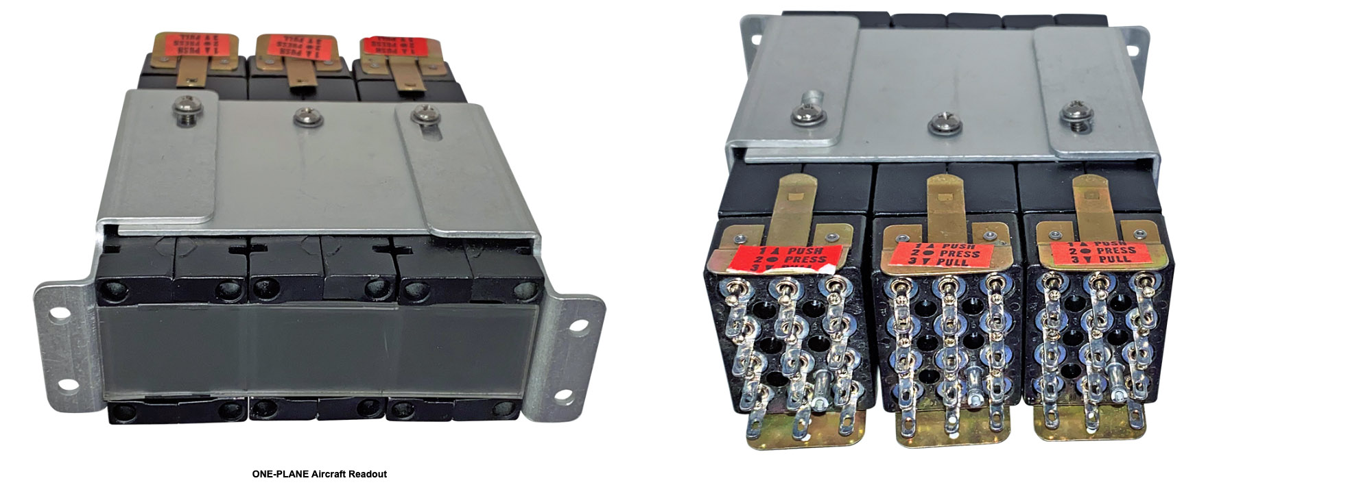
A front and rear view of a surplus aircraft readout. There was only one available, at a price of $150!
The basic idea is that there are ten light bulbs for each display digit. One of them is energized and lights up. It projects a numeric image onto a screen.
In this clock, the relay contacts direct a voltage to select a display digit. The relay coils operate at voltages of 12V, 24V, and 110V, but the display uses light bulbs that run at 6.3V, a common voltage used for vacuum tube filaments and pinball machine lights. You can see why 6.3 was a popular voltage, right?
The back end of two three-digit display modules. On the right, the bundled cable wiring has been replaced by flat ribbon cable with insulation displacement connectors. The remnants of the old ribbon cable from the relays are seen on the left, individually soldered to the display lamp wires.
I had planned to replace the inadequately designed power supply for the clock, and I had figured out how to update the signals to the relay coils, but I had really hoped that I could avoid re-wiring all of the individual connections between the relay contacts and the display bulbs (10 + 6 + 10 + 6 + 10 + 2 of them). I had figured out the connections and how they could be used with the new power supply without having to completely rewire them.
In 1973 I was using some of the latest technology, including “ribbon cable”, an evolutionary step from a tied cable bundle. Individual wires were laid side-by-side and cast in place with an insulating plastic bond. They were also called flat cables. Once again, my source of this unusual wiring system was from my dad’s ham radio shack.
I found them particularly appealing because they were color-coded with the series used to identify resistor values- black, brown, red, orange, yellow, green, blue, violet, gray, white to represent digits 0, 1, 2, … 9. They include the colors of the rainbow, and I recall thinking how nice they will look in the finished clock, which motivated me as I connected them to the stepper relays.
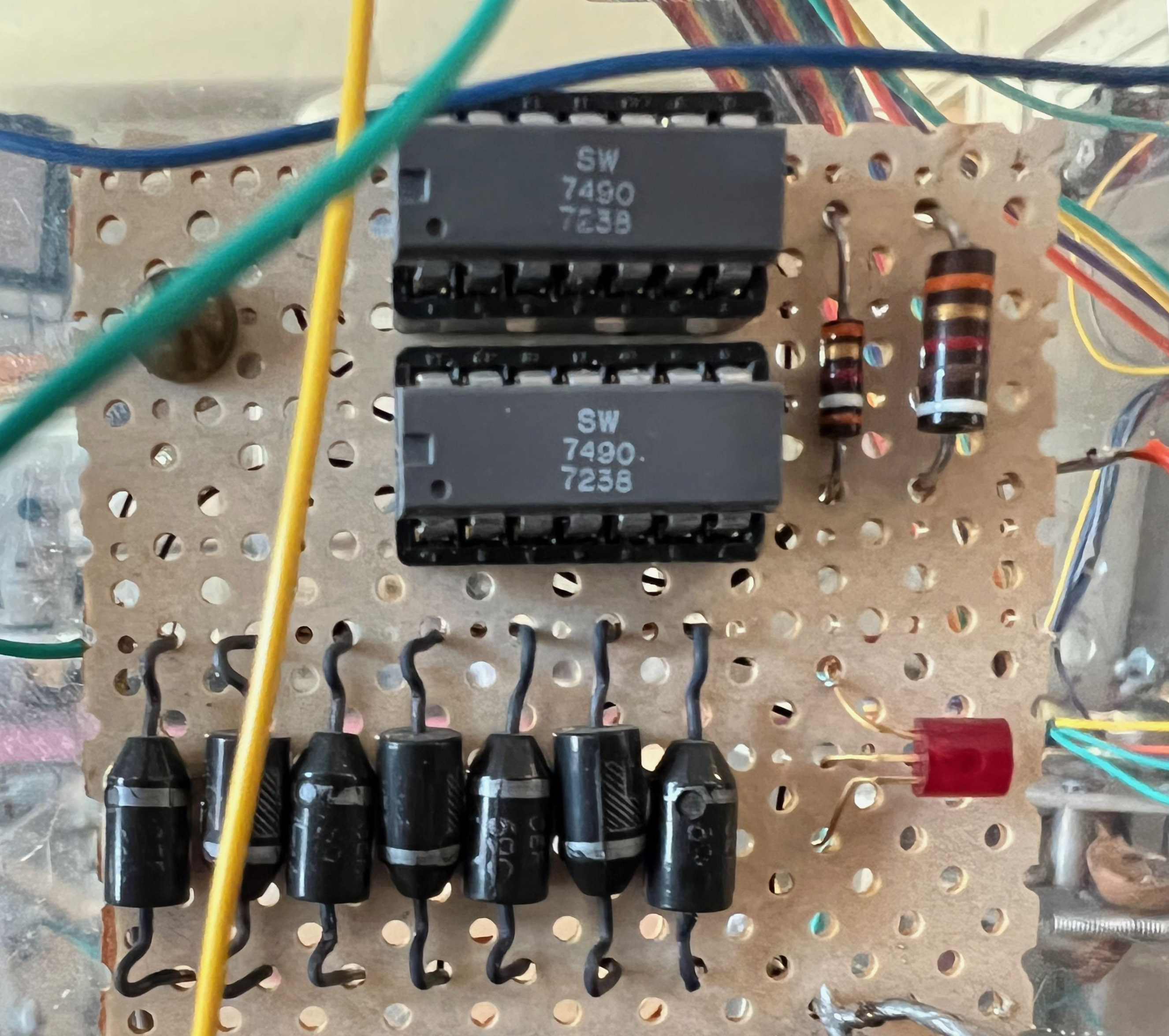
Two 7490 integrated circuits. The date code tells us that they were manufactured in September of 1972.
Although I was unaware of the new integrated voltage regulator circuits when I built this clock, I was familiar with an early series of integrated logic circuits, the 74xx TTL chips (TTL stands for “transistor-transistor-logic”). Again, the ability to replace multiple circuit boards of discrete components that implemented a specific logic function with a single integrated circuit chip, was revolutionizing electronics.
An example is the 7490, a small 14-pin device that implemented logic that could count to ten. I used two of them, configured to count to 60 and then start over. I fed it a clock input that was derived from the household AC line, 60 cycles per second, and it delivered a logic pulse once a second to the first relay in the clock.
I wanted to keep this relic of a circuit in the renovated clock, and so I adapted its input to the AC signal from the new power supply. But I had forgotten the rules for using the ancient TTL logic, which required much higher current than is used today. Modern CMOS logic uses almost zero electrons to do their magic, which is why your phone doesn’t discharge within a few minutes, blistering your hand with the heat.
My first attempt to trigger the old timekeeping logic resulted in paralysis. No ticks.
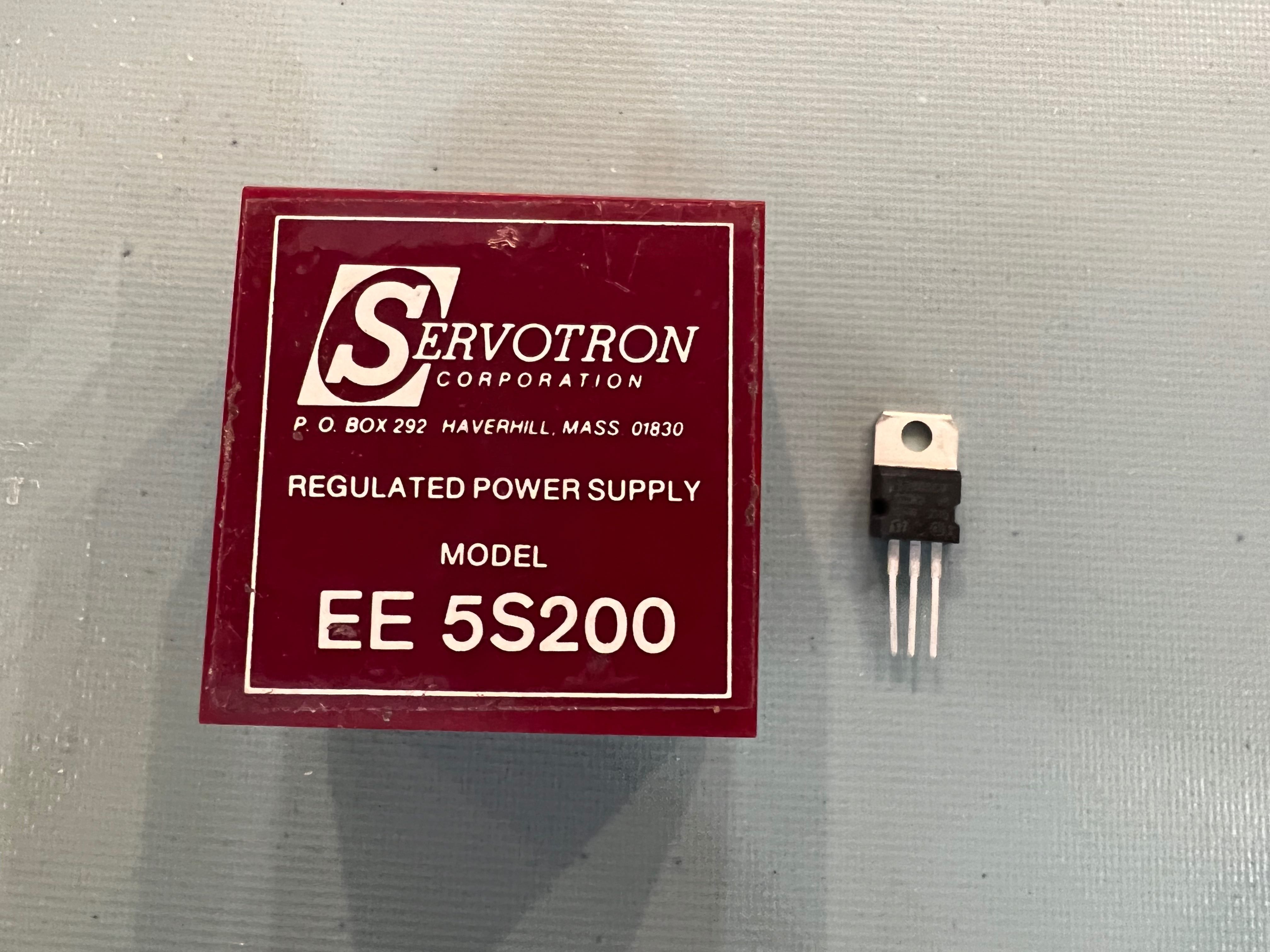
State-of-the-art power supply in 1973 next to a modern (for over 40 years now) voltage regulator.
As I mentioned, I was not skilled in power supply design in 1974. I am still no expert, but I have acquired some familiarity with them over my career. Back then, one needed to understand transformers and bridge rectifiers and capacitors. They were simple, but limited.
Think of your basic plug-in wall charger. A few years ago, they were made of a dense and bulky transformer, diodes, and a capacitor, the smallest components that the designer could find to meet the power requirement. They were not terribly efficient and could only provide a few watts.
Today your cell phone and computer chargers can deliver hundreds of watts but are smaller and lighter weight than those old “wall warts”. They are the beneficiaries of new power supply technology that uses high frequency internal circuits to replace the old iron cores of the 50-60-cycle transformers.
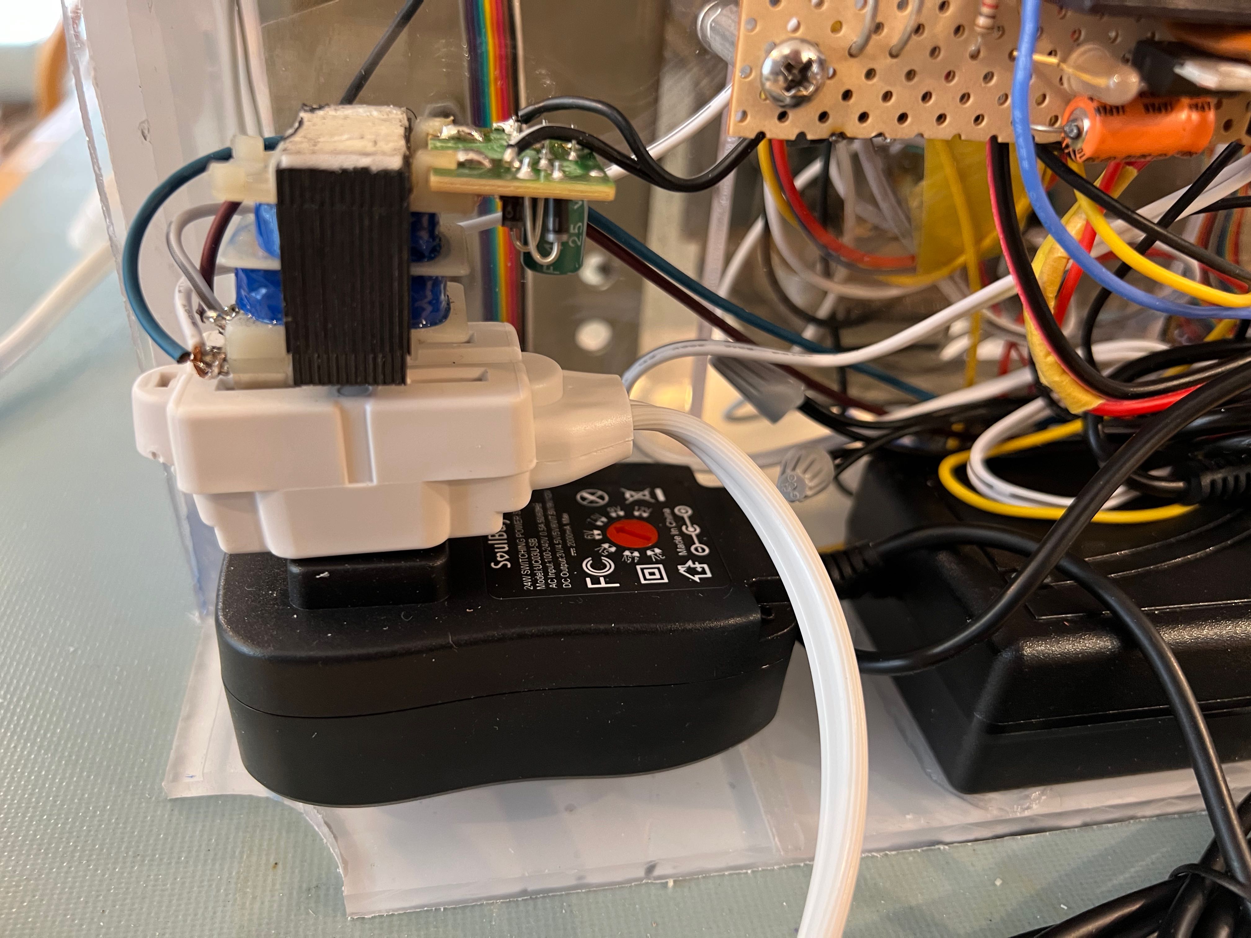
I could now replace my old 24V center-tapped transformer-based power supply with a modern “AC to DC converter” that could provide more power at higher efficiency than was possible back then.
I needed some more voltages: 12V and 5V. The old supply took the “center tap” of the (24V) transformer to provide 12 volts for those relays that needed it. The 5V for the logic circuit that generated the one-second pulse was obtained by a crude arrangement of diodes and resistors powered from the 12V line. I’m amazed it worked.
But that was what was available back then: diodes and resistors. Today it is trivial to generate stable power supplies by using the ubiquitous 78xx series of voltage regulators, a component that has three pins: voltage-in, ground, and voltage-out. These breakthrough parts were first manufactured in the early 1970s, a time when “integrated circuits” had recently been invented and were being applied to an ever-increasing number of applications. In this case, elaborate voltage regulation circuitry that had previously required dozens of discrete components were now implemented by microscopic semiconductor junctions contained on a single “chip”. At the time I built this clock, regulator chips were becoming available, but I did not yet know about them.
Today (and for the last 40+ years), I use the 7805 to provide a +5 volt supply, and a 7812 to generate +12 volts. This will be part of my power supply renovation.
AC to DC converters (black modules) for the renovated clock. One provides 24V, the other supplies the 6.3V for the display lamps. The object plugged on top of the power cord is an isolation transformer that provides the primary timing signal.
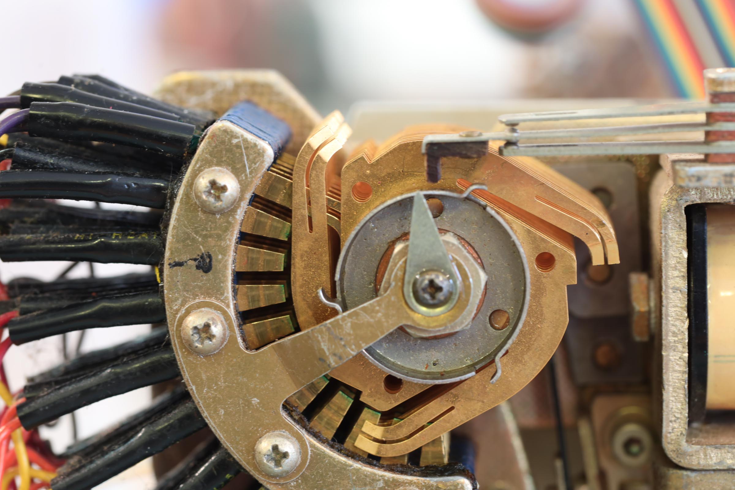
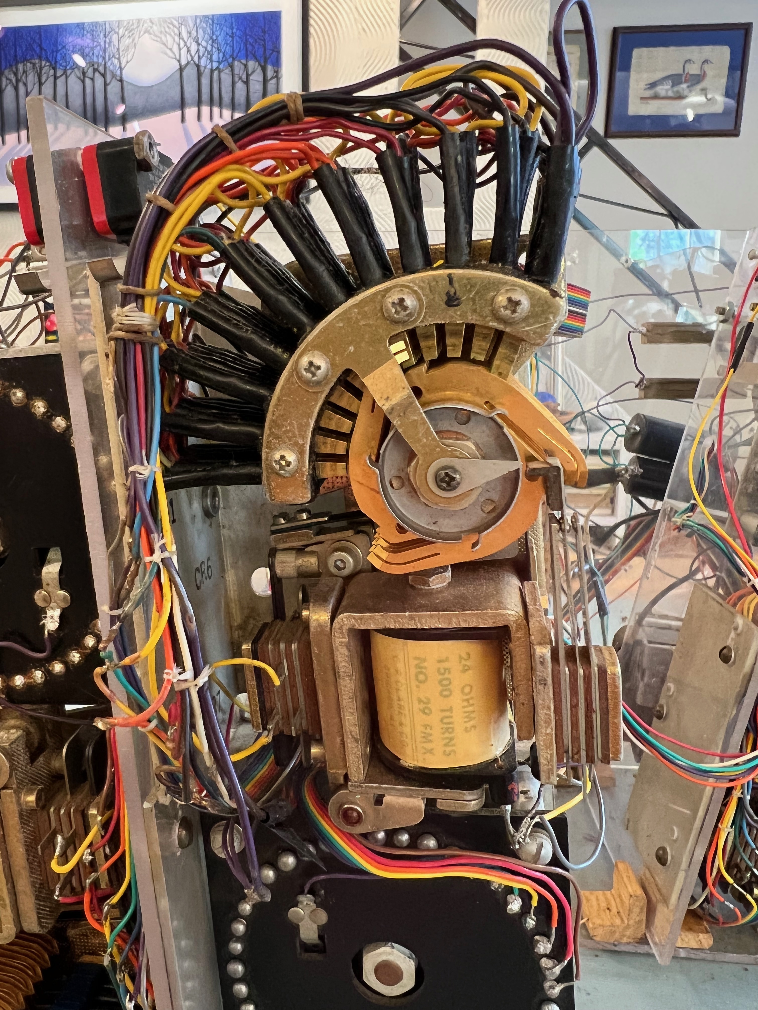
A closeup of the ten-step relay. It moved sluggishly and got held up on the tenth step when the carry contact (upper right) could not close, stopped by the bump on the circular cam.
I re-wired the relay coils for the improved control circuit and hooked up the new power supplies. A set of micro-switches were used for setting the time—they momentarily applied power to the relays with each button push. I could now see if the relays still worked. They did!
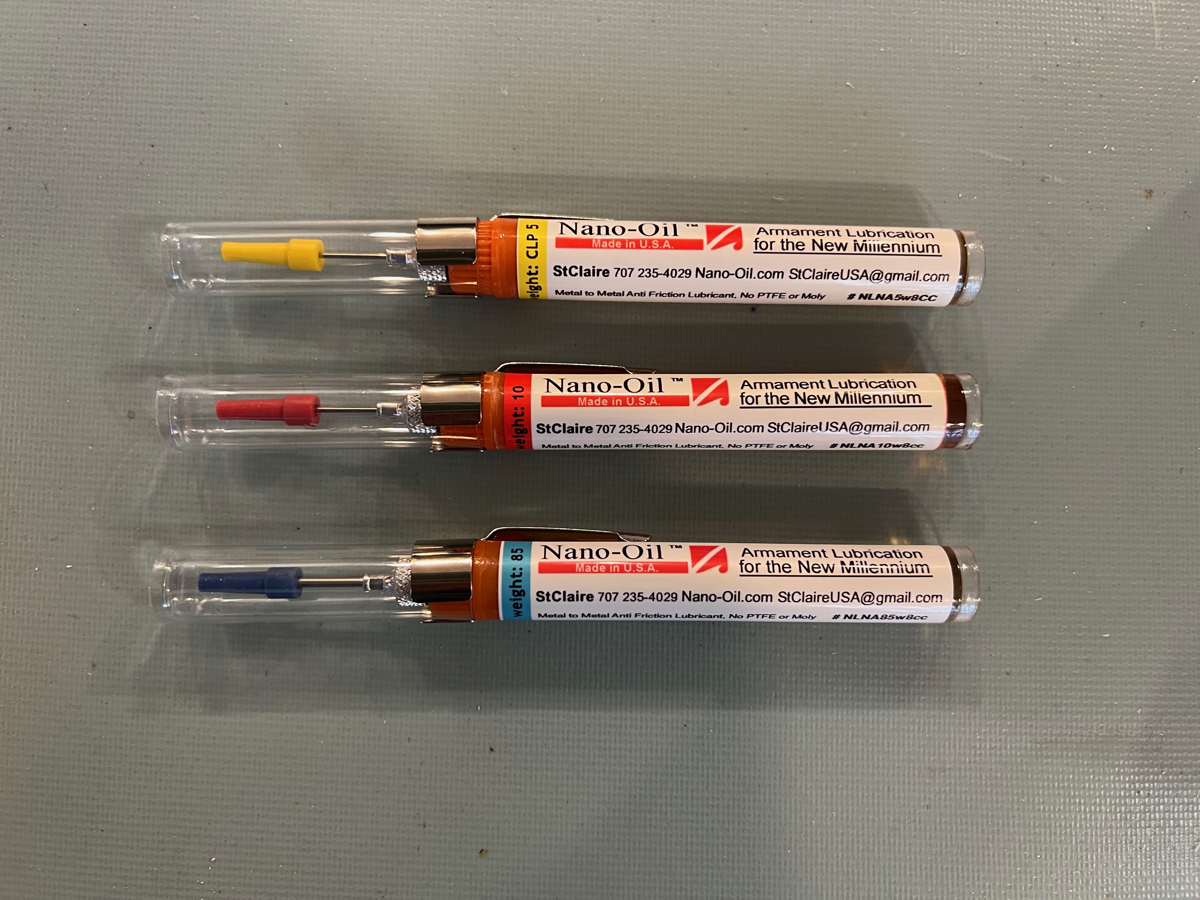
Well, they mostly worked. The contacts had tarnished and needed cleaning, and some of the mechanisms got stuck in one or more positions. I applied the usual treatment for things that stick—WD40, but it was not enough. The lubricant that finally allowed the decade stepper relays to move freely was something called “Nano-Oil”, a substance using “Magnetically induced Molecules of 0.09 microns”, that my son had gifted me a few years back. At the time I wondered what I would use it for, but he evidently saw my future need for it.
“Nano-oil” helped to re-lubricate the moving parts on the relays.
A short video showing the (restored) relay activation and contact movement.
I had no schematic and my memories were vague, but I recalled that there had been three types of relays, all operating at different voltages, which made for a complicated arrangement of relay contacts and coil terminals. There was yet another voltage involved in lighting up the display. I wanted to figure out how I had managed all this complexity back when I barely understood power supplies, and then figure out how to renovate it, with the least amount of re-wiring.
As I went about tracing wires, confirming contacts with an ohm-meter, I gradually built up a re-understanding of how the relays were interconnected. Some of the wires had broken and so I could only guess their destinations. I eventually figured out how the three different relay types managed to propagate the time signal from one level to the next. As I worked on this, there were more than a few times when I wondered “how could this have ever worked?”