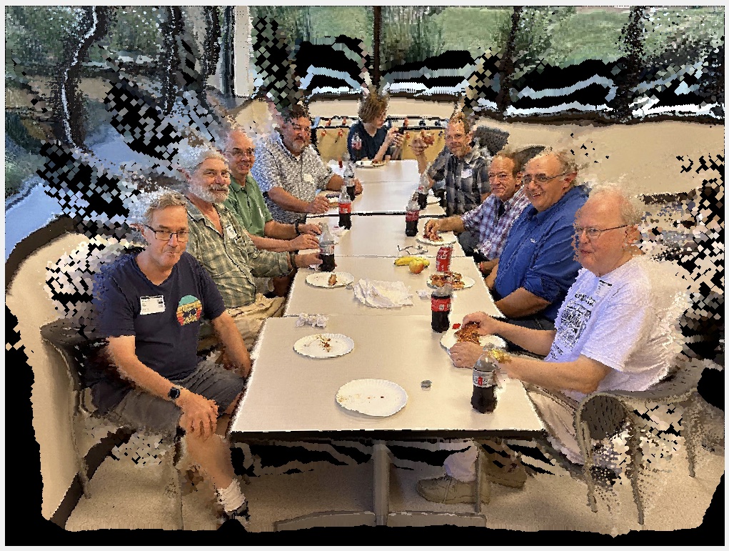
This is a computed image. It started as a snapshot of a group at a lunchroom table. There was nothing particularly significant about it except as a record of a pleasant reunion of this group of old friends. And like many such shots of a group at a long table, it is hard to get them all in the frame and to represent each member in a photogenic pose. In particular, the persons at the far end of the table are lost in the distance. It is particularly noticeable with wide-angle lenses, the default for phone cameras.
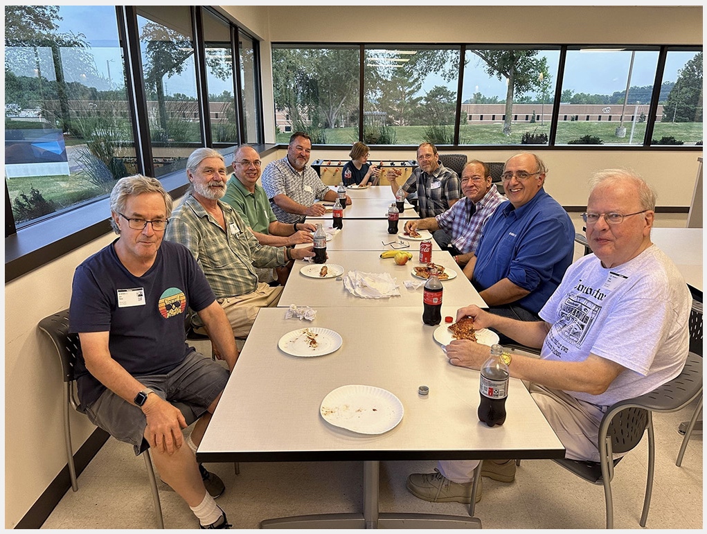
I wondered if I could re-image this scene so that the people are more equally sized, the furthest members are not so small, and the closest not so big. This is what would naturally occur if the photographer used a longer focal length lens and stood further back. This is an account of what I learned.
There are techniques being developed to do this change in perspective (see CompZoom_SIG17 and ZoomShop), but they rely on additional information such as multiple pictures at different distances, or a full depth map that provides the distance from the camera to each object in the scene.
I didn’t have a depth map for this photo, but I have recently encountered a tool to synthetically generate one based on clues in the scene. An AI neural network assists in generating the map. The result is a grayscale image where close objects are light, and far objects are dark. I tried at first to simply invert it so that lighter shades (larger pixel values) are more distant, and darker, low-value pixels are close, and I could assign some nearpoint and farpoint distance values to the scene. This turned out to be problematic: distortions resulted. A better result was obtained by taking the reciprocals of the depth map values first and then scaling them to the desired range.
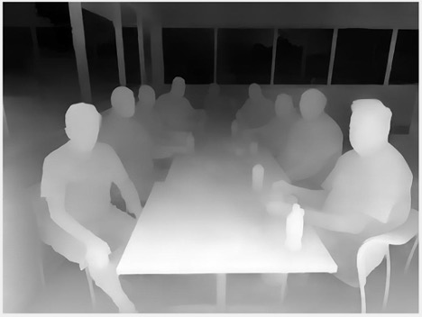
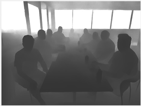
The next step is to generate an “XYZ point cloud”, which as you might guess is the collection of points, each representing a pixel in the image, mapped to a real-world XYZ coordinate. To do this a camera model for how the world is projected onto its sensor is needed, which is then used to reverse-calculate where each pixel in the image came from. I made estimates for Fred’s camera and where he was standing when he took the picture.
The point cloud is like a color image, a 2D array of 3-component entries, except instead of RGB, the elements are XYZ, which means it can be depicted in a 3D representation.
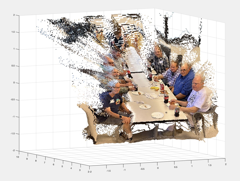
As a check to see if this was on the right track, I attempted to re-create the photo starting from the point cloud data. Applying the parameters for the camera model, the points are projected onto the image plane. After fixing a few bugs, I confirmed that I could make the round trip.
Now that I have a 3D point cloud of the scene, I can consider how it might look if I changed the viewpoint. Of course the point cloud model is sparse, there are no data points representing the back sides of the objects, or anything occluded by them, so I can’t do virtual flyovers like one can through a complete 3D model. But small adjustments should be possible.
The adjustment I wanted was to step back from the scene and zoom in slightly to fill the frame, thereby gaining some foreshortening in the perspective. Here is the result:
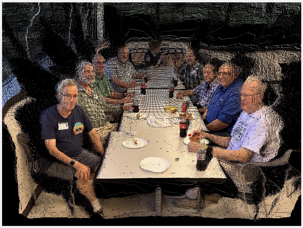
Projecting the point cloud onto a different (virtual) camera, one that is positioned farther back, and using a lens with a longer focal length should give a more “flattened” perspective. Unfortunately, the point cloud is not dense enough to cover all the pixels of the second camera. The pixels with no view of any point in the point cloud remain black.
However, the desired perspective has been achieved: there is less difference in size between nearest and furthest subjects. The parallax has also changed. The nearest subjects have moved “in”, obscuring some of those behind them. They leave behind a cloud of unfilled pixels representing where they were with respect to the original camera. There is also an apparent look “down” on the group. The camera was moved 3 meters back from its original position, along the optic axis line of sight, so the virtual camera is also higher, probably close to ceiling height.
To provide the missing pixels, two strategies were deployed. The first is a “reverse painter’s dilation algorithm”. There are only 256 distinct depth values. They are processed starting from the closest depth layer and proceeding back (hence the “reverse” painter, who normally starts with the furthest objects). The pixels in each depth layer are mapped to their location in the new image being computed. If it has not yet been painted (by a closer layer), it is written to that pixel. This prevents further layers from clobbering objects that are closer.
After a layer has been processed to the image under construction, the pixels in that layer are checked again, this time for any left, right, up or down neighbors that might not be painted yet. If there are neighbor gaps, they are written with the center pixel value. This is effectively a “dilation” operation on the pixels in that depth layer, but selectively so—only unpainted, presumably more distant, pixels are allowed to receive the dilation expansion.
The second infill method is similar to what is done for stereo images that need to fill in the gaps of parallax between left and right images. The unpainted pixels are identified (they still have no color in them even after processing all the depth layers) and in addition to looking for left or right neighbors that have been filled, the up and down neighbors are also checked. If one is found, it is used to fill in the empty pixel. The process can be iterated.
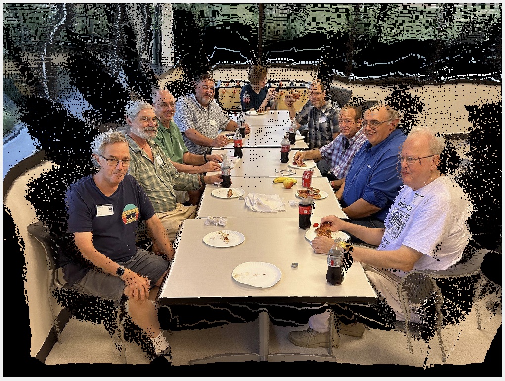
There are plenty of distortions and artifacts in this proof of concept, likely due to the fact that the depth map is inaccurate, having been inferred only by clues in the scene. Another source of error in this test was the jpeg compression artifacts in the depth map. Ringing at edges caused discontinuities near the edges of objects.
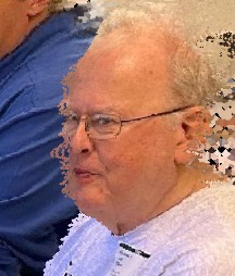
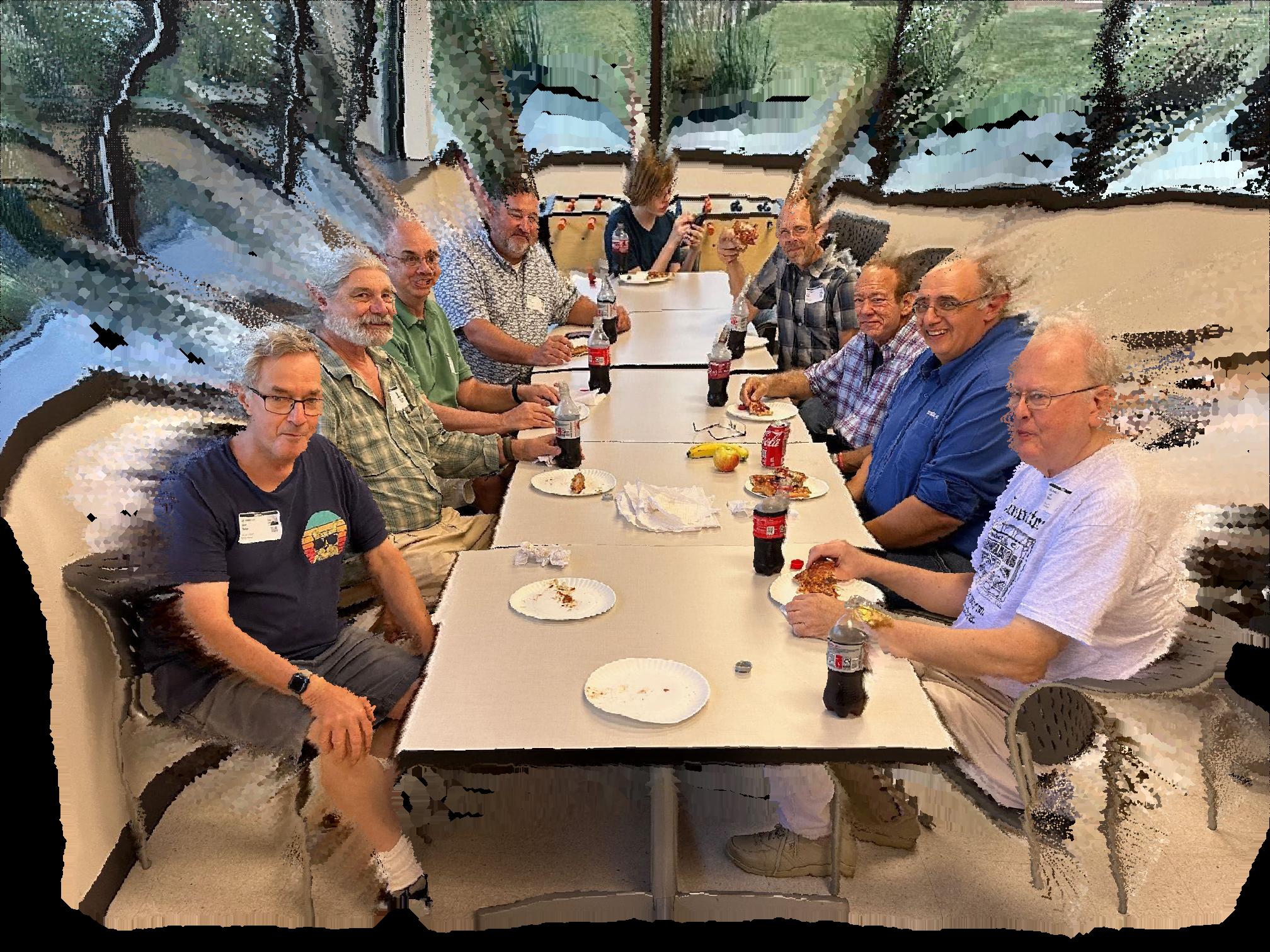
Yes, it looks like they are being extruded into their seats, but it illustrates a computational change of camera, based on the availability of a depth map (which in this case was artificially generated!).
A natural next test is to try this using true depth information, or at least depth inferred from stereo parallax, and encoded more accurately than jpeg. I also want to try a more typical camera move– stepping back but not climbing a ladder (the math will be a little more complex). I will probably do a few more experiments along these lines, just out of curiosity.
This test used a simple dilation method to filI in the missing pixels, but there have been advances in what is called “inpainting”, which examines the nearby scene content and extrapolates it, colors, structures, textures and all, into the gaps.
I won’t be surprised if my next phone camera has this foreshortening feature built-in. Maybe your new camera already does!

